Table of Contents to Clinics
- 2026 Clinic
- June 2026 – Arduinos and AI for Developing a Train Order Signal System, and Other Projects
- May 2026 – Layout Design by Armstrong Squares
- April 2026 – Iron and Steel: The History
- March 2026 – Layout Design and Operations on the BNSF Fall River Division
- February 2026 – Form-Based 3D Printing
- January 2026 – The Station
- 2025 Clinics
- November 2025 – Maritime Railroading, History and Modeling Operations
- October 2025 – What Happens to Your Model Layout & Trains When You Are Gone?
- September 2025 – The Aberdeen and Rockfish Short Line
- August 2025 – Creating Your Own Photo Backdrops
- July 2025 – Capturing Night Scenes
- June 2025 – Capturing the Character of Trinidad, CO. – 1953
- May 2025 – The Missouri Pacific in Colorado
- April 2025 – Atomic-Age Narrow-Gauge: Uranium and the Rio Grande Southern Railroad
- March 2025 – Deep in the Freight Yard
- February 2025 – Civil War Railroads
- January 2025 – My Journey to Modeling in S Scale
- 2024 Clinics
- December 2024 – December Clinic – Gathering of Elves
- November 2024 – November Clinic – Advanced Tools & Tips
- October 2024 – October Clinic – “How did we win the war, Grand Pa?”
- September 2024 – September Clinic – Programming Sound Decoders
- August 2024 – August Picnic – The Infamous Front Range Division Picnic
- July 2024 – July Clinic – How Fred Harvey Opened Up the American Southwest
- June 2024 – June Clinic – Colorado’s Narrow-Gauge Railroads – A Synopsis
- May 2024 – May Clinic – How Geology Determined the Denver-Gunnison Mainline of the DSP&P
- April 2024 – April Clinic – Backdrops: How to Paint and Blend with Mid and Foreground
- March 2024 – March Clinic – The Oregon, California and Eastern comes alive at the Colorado Model Railroad Museum
- February 2024 – February Clinic 1 – Hospital Trains
- February 2024 – February Clinic 2 – Scratch Building with Monster Modelworks Brick Sheet
- February 2024 – February Clinic 3 – Trees, trees, and more trees
- January 2024 – January Clinic – Modeling the ATSF built cars of the 50’s and 60’s
- 2023 Clinics
- December 2023 – December Clinic – Gathering of the Elves
- November 2023 – 1st Mini-Clinic – Sylvan Models HO Scale Laker Class Freighter Kit – Glenn Runkewich
- November 2023 – 2nd Mini-Clinic – Representation of Bath Maine – Rich Gibson
- October 2023 – Canceled
- September 2023 – The Denver and Rio Grande Western (Monarch Branch) – Gary Myers
- August 2023 – Annual Picnic
- July 2023 – Designing a Railroad for Operations Based on the Prototype – Bob Foltz
- June 2023 – Prototype Railroad Experiences and Modeling Perspectives – Kevin Ruble
- May 2023 – The Art and Science of Kit Bashing – Gerry Glancy
- April 2023 – The Evolution of a Railroad, The Education of a Railroader – Scott Ogle
- March 2023 – Tips and Techniques for Building Dual Gauge Turnouts using Fast Tracks Assembly Jigs – Tom George
- February 2023 – Non-Flicker Lighting and Weathering Locomotives – Bill Botkin
- January 2023 – How to Become a Published Author – Jim Chiddix
- 2022 Clinics
Clinics for 2026
Clinic On June 15, 2026
Arduinos and AI for Developing a Train Order Signal System, and Other Projects
Presentation by Rich Gibson and Bill Lund
Bill Lund Biography
Bill has had a lifelong passion for model railroading. Right after high school, he began his career working for the Denver & Rio Grande Western Railroad. After college, he spent the next 25 years in healthcare technology sales, focusing on hospital Clinical Decision Support systems. He concluded his professional career on the commercial pricing technology team at OmniTRAX, where he worked extensively with SQL databases.
He is now retired and enjoys modeling the D&RGW Fourth Division narrow gauge.
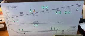
Rich Gibson had a problem in communicating train orders from the Dispatcher’s desk to the stations on line for the Maine Central model railroad. The dispatcher was to hand write the train orders and get them distributed to the appropriate station on the line. By the time the orders were written and delivered to the appropriate station, the train had passed and was further down the line. Maybe a notification system could be developed to notify the train that a train order was coming to that station. This could simply be a directional lighted display to notify the train to hold for the train order. This system would require a minimum of five wires to activate the lights on a panel. The difficulty was that the wiring needed to reach the dispatcher’s desk in the middle of a room and radiate out to the station locations. The low voltage cable is 3/16 inch to ¼ inch in diameter with 6 conductors in the bundle. There are nine stations on the layout, so one can imagine the bundle of cabling needed to reach the dispatcher’s desk. This restricts the location or relocation of the desk. As luck would have it, Rich was traveling with Bill Lund to a train event, and they were able to discuss the situation and the needs for the system.
Bill said let me think about this and he offered up an electronic solution to the system. His thought was to use paired ESP32 computer boards. ESP32 is a powerful, low-cost microcontroller created by Espressif Systems that integrates Wi-Fi and Bluetooth communications. Using this board, the only requirement would be power for the device. The boards are relatively inexpensive but need to be tested before use and care must be taken to guard against static electricity which could damage the circuits.
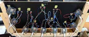
This is where the project becomes interesting. Bill utilized ChatGPT to rough out the system. This plan included the initial code for the boards to make the indicator lights to function at the remote location. The resultant panel is shown below with the reverse showing the wiring involved. It is important to note that each of the LED’s is mounted in a metal ring serving as the touch control for the indicator.
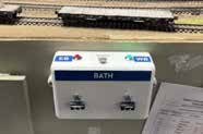
The receiving station located at the appropriate station is a small project box with the ESP32 and lights mounted inside. This also has touch rings at the LED location to toggle the signal. The box was designed and 3D printed by Mike Blalock making this addition to the layout a community affair.
Since this is a wireless system, the control board does not need to be located at the dispatcher’s desk. An operator can function as the dispatcher from any location in the layout room. So, the location could be more centrally located to a number of the train order stations to limit the steps to the train-order-posting.
The ESP32 are inexpensive so each station was paired with a separate ESP32 at the control panel. Each ESP32 could have controlled more than one station. The key to developing the system was the use of AI through ChatGPT to build the program is C++. This is not faultless as AI makes mistakes or really AI does not understand a person’s intentions. It was discovered that AI needs a storyboard approach to the project. One must describe the entire system; including startup sequence, communication flow, touch logic, LED behavior, and error handling. In this case the AI may develop a more complete solution to the coding problem and eliminate a portion of the trial and error. Each of the stations was assigned a unique number to isolate commands to the specific station and required light. Further this information was saved in memory, so that power outages or startup would remember the indications for the stations.
This development was an iterative process and takes time to develop. To that end, make small, surgical code changes, keep your own backup copies of working code, and maintain clear context between sessions. AI is very useful for breaking large problems into small steps, explaining complex ESP32 behavior, designing modular architecture, brainstorming solutions, and ultimately organizing clean code flow. None of the AI programs saves the results from session to session, so it is up to you to create the backup copies to keep moving forward.
Here is a short list of possible projects using the ESP32 and AI coding:
- Wireless DCC Command Station with Wi-Fi Throttles
- Capacitive touch control panels
- Smart LED signal logic
- Automated turntable indexing
- Servo control for semaphores and switch machines
- Real-time scale track weighing system
- Infrared train detection and block occupancy
- Automated water tank system with sound
- Animated coal loading and unloading sequences
- Automated ore tipple and mine operations
Additional uses for AI include:
- Generates realistic switch lists, waybills, and operating session paperwork
- Rewrites complex kit instructions into clear, bulletized steps
- Research historical railroad details, photos, and documentation
- Transforms modern photos into accurate period scenes
- Brainstorms realistic track plans and operational concepts
- Suggests era-appropriate scenery and structures
- Helps troubleshoot DCC, wiring, and electronic problems
- Acts as a real-time modeling companion
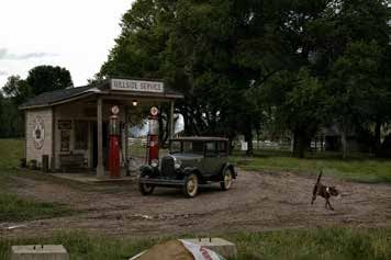
As an example, one can add a period correct business into a photo. The gas station with the glass top pumps was added into the intersection photo for Bill’s layout.
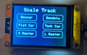
To further illustrate the power of AI, a demonstration of modeling a scale track with an ESP-32 and a CYD display. A story board was assembled to explain to the AI what the end result of the scale track should act and look like.
Scale Track Storyboard
- Screen 1: Main Screen (Train Overview)
- Background: Navy Blue
- Title at top center: “Scale Track” (white text)
- Layout: Two columns with three cars each
- Cars displayed with large text only (no serial numbers here):
- Box Car
- Gondola
- Flat Car
- Tank Car
- Short Reefer
- Long Reefer
- Screen 2: Car Detail Screen
- Background: Navy Blue
- Top left: Back arrow button (white)
- Large text at top: Car Type (e.g. “BOX CAR”)
- Very large weight display in center:
- Normal: White text with green border
- Overweight (5% chance): Blinking Red text + small “OVERWEIGHT” warning in RED
- Bottom section:
- Series range (e.g. “3000 – 3749”)
- Max Weight (e.g. “Max Weight: 72,300 lbs”)
- Car Data Saved:
- Box Car: 3000 – 3749, Max 72,300 lbs
- Gondola: 5500 – 5699, Max 82,500 lbs
- Flat Car: 6500 – 6544, Max 80,000 lbs
- Tank Car: UTLX 11000 – 11058, Max 65,000 lbs
- Short Reefer: 32 – 81, Max 62,000 lbs
- Long Reefer: 150 – 169, Max 84,000 lbs
- Behavior:
- Touch a car on main screen -> goes to detail screen and generates weight
- Tap back arrow -> returns to main screen
- Weight is randomly 80 – 100% of max (normal) or over max (5% chance)
This story board was loaded into Grok and a resulting code was generated for the scale track and the readout. This is a great example of the add on items for a model railroad to add to an operating session. What do you want to happen to the overweight cars?
The resulting code needs to be loaded to the ESP and ChatGPT or Grok will indicate other libraries that need to be loaded with the code into the ESP. this can be done through a USB cable from the computer to the ESP.
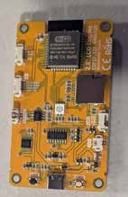
There are several AI programs that can be tried for modeling needs, ChatGPT, Grok, or Claude were mentioned. There was some discussion on the range of the ESP32 board with the answers over 60 feet. This should be sufficient for most model railroad communication needs. One must remember that the antenna is on the reverse of the board and should not be near any metallic shielding.
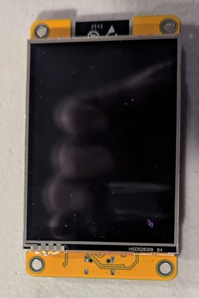
Below is the screen device used for the Weigh Program: FREENOVE Bitcoin Miner Solo Lottery Miner, ESP32 CYD 2.8″ Touch Display 240×320 Pixel TN Screen ILI9341 Driver, Dual-core 32-bit 240 MHz Microcontroller WiFi+BT Programmable, Code Tutorial
To obtain the Arduino IDE go to the following link: arduino.cc/en/software/
To see what the Story Board produced as code for the ESP-32, click on this “here“.
Clinic On May 18, 2026
Layout Design by Armstrong Squares
Rodney Black Biography
Rodney grew up in Iowa, just north of Burlington. The shared Rock Island and CB&Q track ran through his back yard. After succumbing to the fumes (gas and perfume), Rodney went to college, graduate school, marriage, and started a career in software engineering, first at Burroughs Corp, then Bell Labs, working on telecommunications systems. His toddler son revived his interest in trains.
He got hooked on the operations bug on Doug Geiger’s Granite Mountain Ry. Now, the children are grown and left home, but didn’t take the bug with them. He retired for a few months in 2013, but was lured into working at Intermountain Railway, temporarily, part-time. Five years later, Rodney retired permanently but is still practicing his trade by developing signaling software for model railroads. You will not likely see any of his models or photos entered in a contest, so he gives back by making his software (Computer Automated Traffic System, or CATS) freely available to the model railroad community. His interests are in signaling, modern (or recent) equipment and he dabbles in N scale.
Rodney began his presentation with a graphic on the differences between British and American railroads and model railroads. British railways are congested and tangled tracks where as the British model railroads tend to be linear and uncluttered. American railroads tend to be linear straightforward designs with the American representations in the model railroad as a bowl of spaghetti lacking meat sauce or a meatball. The gist of this is that American modelers tend to put too much in too little space.
On to the meat of the program. John Armstrong developed a system for model railroad design. The key to the Armstrong method was the development of givens and druthers. Givens are non-negotiable constraints. These include:
- Space
- Budget
- Time
- Age
- Modeling Skills
Following the givens are the druthers. These are elements that have some flexibility and are basically desirable, but not rigid constraints. These include:
- Modeling Scale
- Era
- Road
- Equipment
- Geographic Location
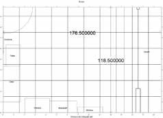
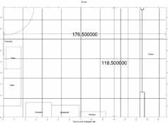
As a result of the COVID lockdown, Rodney had time to plan or dream a layout in a 176.5 inches (14.7 feet) by 118.5 inches (9.875 feet) bedroom. This includes the closet space. The room had furniture in the space. He started with an island layout of 57 inches by 77 inches. This yielded a 212 inch mainline run. The layout would be good for testing equipment but little else. He moved to a layout against the wall of 76 inches by 83 inches. This was still an island, but one side was stranded against the wall. The vexing question was how much layout will fit in a given space?
This leads us to deal with the seven deadly layout temptations. These include:
- Sacrificing aisle access for “one more track”
- Squeezing tracks too close together
- Fudging track radius
- Running tracks too close to the edge
- Ignoring clearances
- Layout too deep to reach all areas
- Inappropriately sharp turnouts
The important elements of track are the 3 dimensions. It has a length, width, and height. This leads to difficulty when dealing with a two-dimensional representation on a track plan. Flex track has directionality as it is intended to curve to one side or the other. This needs to be recognized as the track is being placed. Angles are the Achilles heel of many track plan and layout constructor. Misalignment of the track creates kinks and kinks cause derailments. The most likely place is at entry or exit of curves and diverting routes on turnouts. Vertical curves at elevation changes also causes difficulty with derailments as the entry and exit of the vertical curve needs to be eased to prevent derailments or interference with couplers or low hanging details. Generally, sectional track lines up better than flex track for layouts.
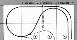
To help with the layout planning, John Armstrong came up with a method of squares. The layout square is the sum of the minimum radius of the layout curve plus two times the minimum track spacing. The radius is part of the layout givens or druthers, and the track spacing can be found in the NMRA Standard RP-7.2 (2017) formerly S-8.
The spacing is also tied to the radius chosen for the layout. The basic square is the size of a 90-degree turn for a double track line. It is important to note that the dimensions given in the Armstrong publication were current in 1989 and do not reflect today’s standard dimensions. The importance is the method not necessarily the specific dimension. The book goes on to give typical layout sizes which would need to be updated for today’s equipment and NMRA standards. The Armstrong book continued on with some sample track geometries that would fit into a standard square. The examples showed interlocking curves utilizing differing elevations. An alternate arrangement for including a turnout within the standard square. Yards and turntables are outliers in the square method as they consume a great deal of space. So, these elements will require special planning and execution. The last example was a convoluted plan that showed the change in direction and examples of where other tracks could come off the looping configuration. Moving into straight track configurations, the main attribute of the straight track is that it is elastic and can connect the resultant squares. Ladders are real estate intensive. They need a lot of room to yield meaningful lengths of track storage. Turnouts have a direction changing component, but do not require as much room as a curve.
Returning to the layout room planning, the difference in the number of squares can be evident with a change in minimum radius. The room considered before would contain 6 X 9 18 inch squares with the 15 inch radius. It would contain 5 X 8 21 inch squares with an 18 inch radius.
The difference is striking between the layout area. John Armstrong went on to define alphabet layouts with an interesting similarity to letters of the alphabet. The jay style is very similar to many small layouts. The difficulty with these plans is that no aisle ways were provided in the minimal plans. In practice the plans need to be enlarged to include spaces for people. The square system is good for estimating the overall size of the layout. The curves are all 90 degrees. Curves greater than or less than 90 degrees change the square size to accommodate the curve. No elevation changes are part of the planning template.
Working on the plan for the given space indicates some compromises with the method. One could work from the interior of the space out, but it was chosen to work from the outside into the space. Using squares to sketch the maximum perimeter to find the desired number of wiggles within space. The goal was not to tile the space but provide curves within the space between tangent track alignment. No interior trackage was planned with this method.
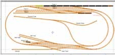
The yards, passing sidings, and spur tracks were not included. The first iteration was more the classic jay configuration. The second and third tries refined the basic shape of the layout with a more curvilinear alignment and shelf layout configuration along the one wall. The final plan is shown below with the addition of industrial spurs, classification yard. and a staging yard.
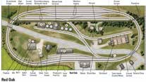
Here we move on to the question of “What space is required for a given layout geometry?” The subject here is the Red Oak layout track plan from “Model Railroader”, dated 2015. This plan was one of the project layouts that were regularly built for the magazine and the video series. The layout was a loop of mainline track with a staging yard behind a low backdrop. The backdrop was penetrated by a spur line with a small yard sharing the staging yard area but not connected to it. The plan was purported to be built on a 36 inch by 80-inch space. The plan was built using Peco turnouts including two curved turnouts. In studying the plan, Rodney found that it did not work with the track geometry. Somewhere the geometry was fudged to fit the plan on the space. Rodney re-planned the layout with more useable yard tracks and without a mid-layout backdrop. The resulting layout takes about two hours to switch.
The squares method leaves a large area as unreachable within the curve, half circle, or full circle. The area would only be useable by violating the minimum radius, or accessing the area from an adjacent tangent. Curved turnouts can help minimize the distance needed between squares.
The design process using squares can be descibed as this. Figure out what is wanted, and define the givens and druthers. Estimate how much of the wants will fit in the given space. The space dimensions need to be determined. Remember the space dimensions do not need to fill the entire room or space. Assign the standard radius when you see the available space. Compute your dimensions of the square. Divide up the space by the square dimensions. Place the squares and sketch the perimeter. Fill in the details.
Utilize the computer programs to your advantage, or invest in a quality electric eraser and eraser shield. Good planning!
The book used as reference for this presentation was “Track Planning for Realistic Operation” by John Armstrong. There are three editions of this book, published first in 1963, second in 1979, and the third edition in 1998.
All illustrations in this article are from Rodney Black.
April Clinic – April 20, 2026
Iron and Steel: The History
Doug Geiger, MMR, Biography

Doug lives in Longmont with his wife Barbara. Other interests besides model railroading (which he lives and breathes almost daily) include submarines, science-fiction books and travel. He was born in Montana, lived in Houston (where he obtained much of his model railroad knowledge) working for Shell Oil and moved to Colorado in 1981. He retired in 1991 and became a househusband.
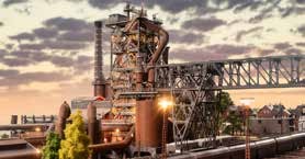
Steel Mills are an important part of railroading. The rails come from the mills along with many of the accessories to the rail network. Steam locomotives used a good deal of this material in their manufacture and maintenance. Importantly for the model railroader are the number and variety of inbound loads and the outbound abundance. Doug has prepared an overview of the subject and has a good deal of insight into the process.
America’s history and development is deeply intertwined with iron and steel. We will trace this fascinating industry through its beginnings pre-1900 and what steel was making back then. Then in 1901, US Steel was formed, the largest corporation at that time in the world. Some of US Steel’s competitors will be deliberated, with emphasis on Bethlehem Steel and WWI. Next comes WWII and its insatiable demand for steel and how the industry responded. The peak of steel production in the post-war period is then covered. Finally, we will see the decline of this industry with the introduction of foreign imports and both labor and management unwise decisions. Unions and strikes will also be seen along the way. Time permitting, some current events can also be
discussed. Join us as we explore the rich history of steelmaking in America.
Doug Geiger presented his clinic on the Iron and Steel Industry. The focus was on the industry itself and not so much about the railroad emphasis. These industries had a long history and development prior to railroad involvement, but the railroads helped the industry grow and prosper as the transportation of raw material and finished goods was more efficient with rail transport.
The earliest form of iron came from meteorites. The material was found to be useful for weapons. Those being Damascus steel blades, Sheffield steel, and Wilkinson sword all from the 1700’s. In England, in the 1700’s, the iron industry had poor working conditions, with environmental hazards. A number of nationalities worked in the industry with the primary product being iron rail. Steel was very costly at this point and very labor intensive. Basically, the furnace for making the iron was an open top tapered oven. The material was fed by hand through the open top and the iron material was removed from the bottom.
Blister steel was made by layering molten iron with charcoal. The product was re-heated and formed crude steel.
The industry made its way to the colonies with Jamestown producing iron in the New World. The labor was largely Eastern European with the bosses being Welsh, Scottish, or German, making the work an industrial serfdom. Tariffs were levied on iron products from England to other nations including the new world colonies. This was a part of the reason for the revolution.
The English used charcoal for fuel, then coal, and finally, coke in the production of pig iron. This greatly increased production of iron in the 1800’s. An early blast furnace was loaded from the top with iron ore, lime, and charcoal. The blast part of the furnace was a bellows that was used to force air into the chamber. Slag was bled off the bottom separate from the production iron. An example of an early blast furnace can be found at the Saugus Iron Works National Historic Site. This is located 10 miles north of Boston. The site includes the forge, rolling mill, and slitting mill. The 1800’s mills were crude affairs that were prone to break downs or explosions. The transportation of the iron was largely by water.
In the United States, the industry expanded with Bethlehem Steel started in 1857. This was followed closely by Tennessee Coal and Iron in Birmingham, Alabama in 1860. Carnegie Steel had one of seven blast furnaces located in Pittsburgh, Pennsylvania in 1865. Illinois Steel was formed in 1889 in the Chicago area. Interjected into this expansion was the Civil War, the North dominated iron production with over 1100 factories in Pittsburgh. More than 20,000 northern workers were in the iron industries. The South had six iron factories at the beginning of the war. The one remaining plant in the south is Tredegar Iron Works. Of course, one of the famous sea battles was the Ironclad contest, between the Monitor and the Merrimac. The iron industry was only one of the mismatched industrial areas between the North and South. Early blast furnaces were shown with the manual loading using skip hoists and added heaters to the air prior to injecting. Some containment measures were added to control the carbon monoxide emissions.
Steel at this point was made by puddling the iron by adding coal or charcoal and additional limestone to a small mass. This was worked back and forth in and outside of the furnace with the result being about a bowling ball size mass of steel.
Crucible steel was made by adding sand, glass, and ash in a crucible with the molten iron. As the additives were incorporated the carbon content was reduced forming a crude steel. Two individuals were working on an improved process for producing steel in what became known as the Bessemer process. William Kelly was an Irish Pittsburgh steel maker, who came up with the process. He did not patent the idea. Sir Henry Bessemer was an English steel maker that did patent the process. Kelly later won the patent back, but we still know the process as the Bessemer. This process involves forcing hot air into pig iron in a converter, oxidizing the impurities, and creating steel. The first plant in Britain was started in 1855 with the American plant established in 1872.
An improvement in material for the iron/steel manufacturing was the substitution of coke for coal or charcoal. The coke was made in beehive coke ovens which were used until 1972 in the U.S. and until 1996 in China. Modern coke batteries are a series of tall ovens charged from the top and discharged from the bottom. The coke needs to be quenched immediately upon removal. The scene in 1892 includes Carnegie Steel. Andrew Carnegie is the head of the company. He is dependent on Henry Clay Frick as the king of coke. They hire Charles Schwab to run the plant. He is an extravagant spender, but very wealthy. Carnegie gets tired of the spending and fires him. He goes to Bethlehem Steel. Both Carnegie and Frick are not friendly to labor and unions. They are interested in the lowest cost possible to produce the product. Key plants for Carnegie Steel were located in the Monongahela Valley as Homestead established 1888 and Edgar Thomson established in 1890. Elsewhere in the U.S., Bethlehem Steel began in 1899, and Inland Steel started in 1898.
In 1892, the Great Homestead Strike was started in July. This started in March – May as the 10,000 coal miners went on strike. The iron workers had the Amalgamated Association of Iron and Steel Workers to represent them. Carnegie declared a 15% reduction in wages due to a drop in steel prices. The average laborer made 14 cents per hour, or $524/year, skilled crafts made $1.48/hour, or $5,500/year. This compares to Carnegie at $3,500,000 per year. 300 Pinkertons were hired to re-take the plant. The workers resisted and stopped the Pinkertons and scabs from entering the plant. With an appeal to the governor, 7000 militia were sent to the plant to allow scabs to enter and keep the plant in production. The militia incited mob rule and the townspeople supported the strike. With no financial assistance, the workers had no income. The company just waited out the strikers. An assassination attempt was carried out on Frick by an anarchist. Public thought this was the strikers. As a footnote to this madness, rich iron ore was found in the Mesabi Range.
U.S. Steel is formed in 1901 by J.P. Morgan. He purchased Carnegie Steel companies along with others to assemble 149 steel plants across the U.S.. This is to control 65% of the U.S. steel industry employing 168,000 workers. Wall Street dubbed this “The Corporation”. The corporation had 84 blast furnaces, 112 ships, and 1000 miles of railroad. This was the largest corporation in the world with a value equal to 1% of the global wealth. This cost $480,000,000 in 1901. Albert Gary was hired to run the corporation. A good book on the subject is “The Corporation” by Brian Apelt.
During the same time frame, Bethlehem Steel developed the wide flange structural beam. This product had two parallel flanges separated by a web. The hallmark is the relatively small fillets of material connecting the flanges to the web. This product was put to use in the Empire State Building, Golden Gate Bridge, and Madison Square Garden. The shapes and weights are codified in the “American Institute of Steel Construction, Steel Construction Manual”.
World War One covered the years 1914-1918. The steel industry provided a good deal of material for the war effort. Steel was used in aircraft engines, helmets, armor plating, and heavy artillery guns. Bethlehem Steel made 24,000 shells per day and attained a 29% profit. The National War Labor Board started during this period so that factories could run 24 hours per day. This lead to 8 hour shifts and finally to 8 hour days for labor. After World War I, steel production shifted to sheet steel for automobile manufacturing. Parallel to this demand was the need for appliances again using sheet steel in manufacturing.
A new product was developed, beer in steel cans, which greatly increased the need for steel material. This period also gave rise to the integrated steel mill where products were produced in line of the plants. This meant that beams, nails, wire, sheet steel and other products were produced directly from the blast furnaces, coke ovens, rolling mills, and treatment plants delivered by internal railroads with incoming raw materials, and resultant products being shipped by rail or ships. Unions finally got the National Labor Relations Board in 1935 through the Wagner Act. The unions discovered that they had political power.
Part of the folklore surrounding the steel industry was Joe Magarac. He was able to play pat-a- cake with white hot steel. He was credited with supplying Paul Bunyon’s axe.
World War II begins. The War Production Board is created in January 1942. The Board banned steel pots, mailboxes, metal chairs, and automobiles. The National Defense Commission ordered steel companies to abide by the Wagner Act or not be considered for defense contracts. Steel manufacturers made 32 billion dollars in profit during the War. This was with price stabilization in place. German steel output exceeded U.S. production at the beginning of the War. New steel plants were built by the government, Defense Plant Corporation, including Geneva Steel in Utah and Kaiser Steel in California. Kaiser Permanente was started by Kaiser for health care in the ship yards and extended to the steel plant. The War years were concentrated on production not innovation. U.S. Steel buys Geneva Steel at the end of the War for pennies on the dollar, deemed war surplus.
Steel production continued to expand after the War, with 73 blast furnaces in Pennsylvania and 49 in Ohio. Record production of steel in 1950 at 100 million tons. This total climbed to 121 million tons in 1980. However, all good things come to an end as the total in 1982 had dropped to 73 million tons. Remember the U.S. was focused on production not innovation. Innovation was natural in the rest of the world as the war destroyed plant and facilities were rebuilt using the newest methods and technologies. Seven of the 10 highest paid business executives were Bethlehem Steel men in 1957. The Taft-Hartley Act restricted union activities with no more wild-cat strikes. Look out here they come, 1958-1962, China’s Great Leap Forward, diverted labor and focus from agricultural activities to industrial projects, including backyard steel furnaces.
During the peak of production period from 1940-1970, steel making was found in 14 U.S. cities and one Canadian Province. Nine different companies were involved in the industry. This production brought about a different problem. The iron ore in the Mesabi range was becoming depleted and so other sources were found in Cuba and Venezuela. The alternate to loose iron ore was Taconite rock. This is a very hard dense iron bearing rock and was considered waste. With some research, a way to break the rock was found and if pulverized and mixed with clay the material would form pellets. These could be used in the furnaces and were easier to handle than the ore itself. “Taconite: New Life for Minnesota’s Iron Range” is an excellent book on the subject and offers insight into the change in raw material.
The peak production period had other issues. Labor would strike. In 1959, over 500,000 coal and steel workers went on strike for four months. Major concessions were obtained by the unions as a result. Wages were increased particularly during steel price increases. No reduction of wages results when steel prices go down. This is a period of record profits, and no one believed that this would ever change. Management paid themselves first and labor got increases as well.
Bethlehem Steel established a laboratory, Homer Labs, in Pennsylvania as the largest steel research lab in the world. It was constructed in 1961 with 220,000 square feet of lab and office space. It remained in operation until 1982. The campus is now in part used by Lehigh University.
The presentation continued with a review of some steel operations. Beginning in 1959, imported steel is making inroads into American manufacturing. The EPA is formed and the impact of air and water quality regulations is beginning to be felt. This push increases in the 1970’s costing the steel industry a lot of money. The result is that many steel plants close. Nippon Steel was the largest steel manufacturer in 1971 leaving US Steel in the dust.
The steel industry, in general, did not forecast the demand correctly. The money was too good and flowing so well, no end could be seen.
The decline in the 1980’s was a long time coming. Unions were very strong. Section 2B indicated that if new technology was put in place and the union worker lost his job, he was to be continued to be paid. Union rules segregated functions in the work place with electricians needed to plug in the coffee pot. This result was a reluctance to innovate and a slowing of productivity. Workers were given 13 weeks paid leave after 5 years on the job. There was plenty of blame to go around with labor blaming management and management blaming labor for the sorry mess.
Population is shifting as 20 percent of Pittsburgh leaves between 1981 and 1986, with 150,000 steel workers unemployed. In 1980, US Steel buys Marathon Oil as the corporation needs to make money not steel.
The decline continues as new technology reduces profits, so Americans are slow to innovate. Research is cut as the profits are not there to support the costs. There are changes in the market, as beer moves to aluminum cans, and cars utilize more plastics.
Bethlehem Steel Sparrow Point Complex contained the world’s largest blast furnace feeding a continuous stream of iron. The complex began in 1891 to produce steel rail and by 2013 the entire complex was gone. It was reduced to an environmental clean up site.
Bethlehem Steel’s main plant was located in Bethlehem, PA started in 1858. In 1995 the plant closed and today it is a casino. Evidently, it has risen to a higher calling.
The Martin Tower was the headquarters of Bethlehem Steel, constructed in 1972 and demolished in 2019. The company was totally gone by 2003.
Rebirth of American steel started in 1960’s with electric arc furnaces utilizing strap steel for the raw material. They are continuous casting operations. Today there are 25 Nucor steel locations. This is a non-union shop offering competitive wages. Executives get no historic perks like autos, or golf club memberships. By 1998, these Nucor mills make 50% of American steel.
The current state is that China and Japan make the most of the world’s steel in blast furnaces. Here in America, we use mostly scrap steel for our production. Specialty steels and applications are very common. Tariffs have been in place since 1840, ranging from 10 to 45%. There are a handful of steel companies in the world.
At this time, there are 12 active blast furnaces in the U.S.. This is a fluid situation with plants closing all the time. USS still has a coke works in Clairton, PA with a poor safety history. It seems to blow up about every ten years.
Iron and steel technology has evolved over the years from the basic puddling to the electric arc furnace of today.
Doug gave us a look at a reading list for additional information. “Steel from Mine to Mill , the metal that made America”, “American Steel”, Nucor’s beginnings, “And the Wolf Finally Came, the decline of the American steel industry”, “Sparrows Point, Making Steel – Rise and Ruin of American Industrial Might”, and “Homestead, the Glory and Tragedy of an American Steel Town”.
For those HO modelers that are interested in modeling a furnace, Faller announced that the 2026 model of the year is the Blast Furnace with a Casting Hall, part no. 130026 with a companion kit part no. 180721, the technology kit which includes lights and animation to add to the blast furnace.
March Clinic – March 16, 2026
Layout Design and Operations on the BNSF Fall River Division
John Parker Biography
John Parker has a life-long passion for the model railroad hobby. He has been retired for five years working for a large global technology company. John is married with two adult children. In his “spare time,” he enjoys fly fishing, hiking, and spending time with his golden retriever.
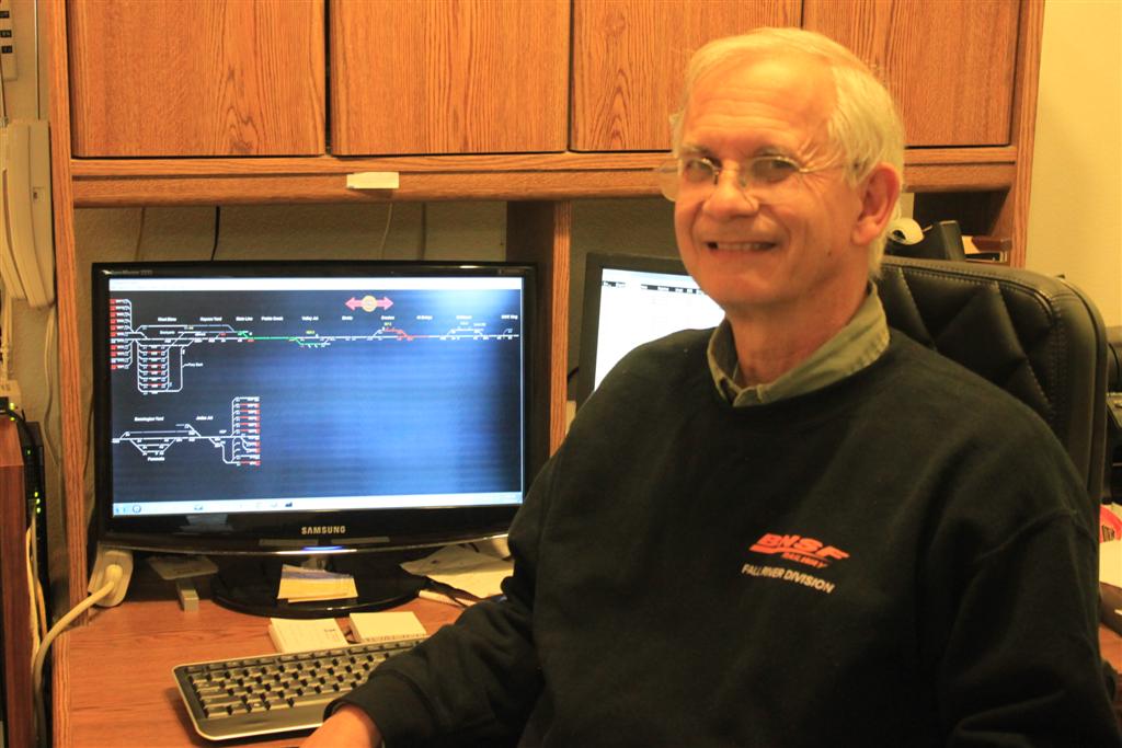
John Parker’s BNSF Fall River Division is a prototype-based freelance representation of the BNSF Railway operating between the Midwest and points north through the Pacific Northwest. The time frame is Summer of 2022 when unit coal, intermodal, Amtrak, and mixed freight trains are frequently seen on the Fall River Division. Several railroads such as the Montana Rail Link and Iowa Interstate interchange with the BNSF, and the Union Pacific has trackage rights over a portion of the Division. The layout was designed for operations and is regularly operated by a crew of 18 to 20 people. This clinic will illustrate the layout’s design for these operating sessions. The discussion will include typical operations on the layout.
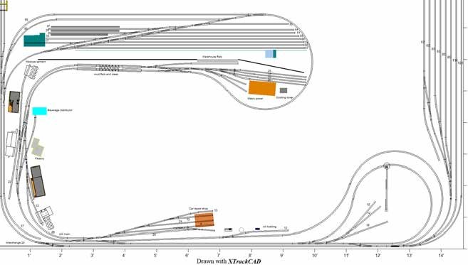
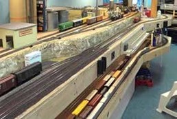
John Parker gave us the clinic on his BNSF Fall River Division. This model railway occupies the lower level of his residence. In a way, that is not correct, as the house design was developed as a cover for the railroad. As part of the presentation, some trivia was added to the presentation. The first of these is what year the BNSF was formed through merger of BN and AT&SF, which is 1995. It seems long ago and yet not that far in the past. The layout overview is:
- A “Modern” Prototype Freelance Model Railroad, that is built to mimic locations without actual prototypical structures and trackwork.
- The layout was designed & built for operations
- The aisle widths and locations where people congregate designed for “People First”
- Construction started in 2008
- Modern/Custom CTC Controlled layout
- The design included branch lines, interchange locations and trackage rights
- Multi-Level (Mushroom) Layout Design Goals:
- Maximize mainline length
- Increase distance between locations
- Provide for long mainline runs & switching
- Create a feeling of “isolation” for operators
- A few more statistics for the layout:
- 2700 square foot layout footprint in 3000 overall square feet.
- 120+ locomotives & 1200+ freight cars.
- 21+ mainline scale miles
- Primary lighting is daylight color tone LEDs with night lighting in blue LEDs.
- 48” and 56” track height with aisle boosters for upper sections.
- 11 DCC boosters with 50+ circuit breaker power districts.
- Increasing wireless access for WIFI throttle use.
- Has hosted over 160 operating sessions – bringing together friends, acquaintances, and the worldwide community of fellow model railroaders.

The layout is a proto-freelance layout on a layout spectrum. What is important about this type of layout is that the owner wishes to emphasize only aspects of prototypical operations through the use of trackwork, equipment, industries, and other areas of operations to allow freedom in the fun value of model railroading. This allows flexibility in eras. The owner can change the era at will. Place or location names are made up and don’t represent any specific locale. He has used names of specific equipment that he likes, or career or railroad mentors. His industry preferences are toward larger industries with many car location spots as opposed to smaller industries with few car spots.
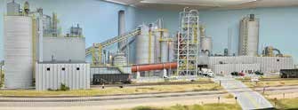
An example of this is the Cemex plant on the layout. Cemex is a real company with large plants located around the country. He used the Lyons location as a model for his representation of the plant.
His representation of Maxxum petroleum gathered too much attention from Maxxum themselves as they alleged infringement on their properties. After some meeting on this they agreed that the model in the basement was not infringement on their properties. This portion of the layout tends to be more prototypical than freelance.
The layout encompasses a variety of scenery types, so it includes Midwest, open prairie, and rocky mountains scenes. The scenery then is more freelance then prototypical.
The equipment selections for the layout are representative of the BNSF in 2018 with about 95% accuracy. The roster includes a Tier 4 SMURF BNSF locomotive in the primary blue paint scheme. This puts the equipment more to the prototypical side of the modeling spectrum. This Prototype-Freelance approach is suited to John’s modeling.
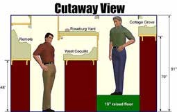
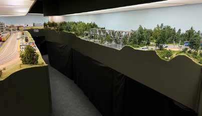
This layout is a mushroom design as a multi-level layout. This gives a single or double level along the perimeter walls with a double level peninsula down the center of the room. By utilizing careful track planning the aisles can vary to allow for extra room at congestion points like switching yards or large industry areas. As you can see in the cutaway view the high ceilings in the layout area are essential to provide for the varying track height. This approach allows for the design to plan for people first and not track. The idea is to direct people to the action on the layout, create a comfortable space, guide visitors, and get them caught up in the action. John was out on the construction site each day during the construction process to assure that his plan was followed. The mushroom design was completed using L- girder construction with 48” and 56” track heights. A 16” raised floor was constructed for the higher track areas. To help define working space at the layout, mats were placed on the floor to define the working area. Curved corners are used to facilitate movement, and alcoves were developed where people need to stand for a while. Electrical circuits are grouped on a wall to keep all power at a common point. The curvilinear nature of the track plan was to create a feeling of isolation keeping the operators in the scene and gives a perception of longer trains and length in the distance. The layout makes use of “negative space” or the spaces between places. This is where the scene is simply scenery and track without any work areas. The operator needs to keep moving though with the train. Wayfinding is facilitated by fascia mounted panels and signage.
The traffic center is the location of active staging and the hub for the computer generated crew paperwork. This is the management center of the layout. Crews never interact with the staging. The crew leaves the train at designated points without entering the yard.
To have a comfortable environment for the operating crew, it is essential to manage the HVAC system for the event and pre-set the temperature for the area. Provisions should be made for operator safety including first aid kit, fire extinguishers, smoke detectors, and emergency lighting. This includes a crew change lounge. Keep the area organized and clean to eliminate distractions.
Operations is primarily to have fun and prototypically simulating operations of a full size railroad. It takes about 20 people to operate the layout with flexibility to have plus or minus five operators. Prototype Practices for operations include use of CTC Traffic Control/Authority, Train/Freight Car Handling, Paperwork, and Two-way Radios. The use of Special Instructions, Forms A/B, and Bulletins are common during the operating sessions. The crew selection is based on seniority with some positions being two person jobs. There are a variety of jobs available for each session with some yard work and other crews operating. The crews move between crew change points without interaction with the yard. Seniority is earned by work sessions, and event participation. Jobs are one or two points per session with adjustment for distance variables. Guest operators are welcomed by making them comfortable, reviewing the session prior to start, and adding seniority points for returning visits. An application keeps track of the crew and points for each session and keeps the crew calls organized.
Car forwarding is done in real time with JMRI Operations Pro by the traffic manager. The report calls out the set outs and pickups along the route. Multiple printers are located around the layout to allow communication at the train location.
Additional trains may be run to match outdoor conditions. These include a fire train for high wind days, a snow plow train for seasonal snow conditions, and at any time a maintenance of way closure for maintenance work. A track geometry train can be used from time to time. A high railer truck can appear at any time.
Technology is used on the layout to monitor activities such as coal car loading. Defect detectors are stationed around the layout to keep track of equipment difficulties such as hot boxes, shifted loads, temperature, bad order cars, and coal protection cars (set out to make up full contract requirements). A track scale is located to weight cars based on a simulated weight. Speedometers are found on the main line to help define the high-speed main line and speeds are noted on the timetable.
It is all about having Fun! See more at: www.bnsfrr.net and https://www.facebook.com/Fallriverdiv/
February Clinic – February 16, 2026
Form-Based 3D Printing
Dave Ackmann Biography
Dave Ackmann is a member of the Gateway Division of the NMRA in St Louis, Missouri, where he serves as the Chairman of the Achievement Program. His railroad is the Baden, Vogt & DeSmet, a 250 square foot freelance layout in HO, utilizing DCC. Dave has received the AP Certificates of Electrical Engineering, Author, Structures and Volunteer, having taught over 60 live and virtual clinics since COVID. He holds a Bachelor’s degree in Mechanical Engineering, and Master’s in Computer Science, and particularly enjoys creating model railroad structures using 3D printing.
Have you tried Dave Ackmann’s form-based technique for creating model railroad structures for 3D printing? Introduced in the summer of 2022, Dave’s “Generator” programs make it easy to fill out a form with specifications for walls, roofing, windows and more, and push a button to get a 3D model. After reviewing the basics, you will see what Dave has been developing since then: Rafters, Canopies, Staircases, Louvers and more. Learn how to combine simple “primitive design elements” into more complex structures. If you are interested in printing your own custom designed structures but were reluctant to invest in learning Computer Aided Design, this clinic is for you. You can see more at: http://daackm.github.io.
January Clinic – January 19, 2026
The Station
Gary Myers Biography
Currently, Gary is living in Aurora with his wife, Michelle. We have two little Shih-Tzu bothers, Thor & Loki. My son Alex, 31, lives in north Detroit. I am on my 5th Ford Mustang, a yellow 2005 GT.
Gary grew up in Michigan, BA in Aerospace Engineering at University of Michigan. From 1981-1985, he lived in the Bay Area- Sunnyvale, CA and worked at Lockheed Missiles and Space, on spacecraft and Titan 34B launches from the Blue Cube (later Onizucka AFS).
He moved to Denver in January 1986 and has been here ever since. Worked at Martin Marietta, Lockheed Martin, and United Launch Alliance until 2016. Worked on trajectory analysis for Titan IV, Titan II, Atlas IIAS, Atlas III and Atlas V rockets. Gary earned his Master’s Degree in Space Operations at the University of Colorado.
Since 2017, he has been working at the Aerospace Data Facility, in Buckley Space Force
Base. His focus has been cyber hardening of industrial control systems.
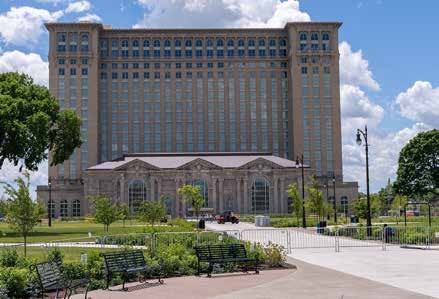
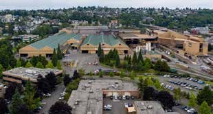
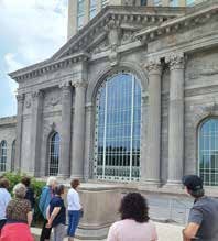
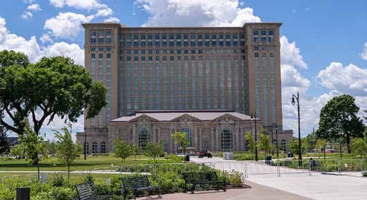
Gary will give us his presentation on “A brief history of the Michigan Central Station in Detroit Michigan”. The Michigan Central Station, also called the Penn Central Station, was constructed in 1913. It was at one point the tallest railway station in the world. The irony is that this monumental building was located in the city that was instrumental in giving automobile transportation to the masses. This made the building and its function obsolete. It is in the continuing process of rehabilitation as part of a multi-use campus.
The station was formally dedicated on January 4, 1914, and remained in service until January 1988. The station building consisted of a train depot and an office tower above two mezzanine levels. The Beaux-Arts style architecture was designed by the architects that worked on New York City’s Grand Central Station. The station was rushed into service as the original depot located downtown was closed by fire. Because of the rushed opening, the station was never finished with the upper floors left vacant. The cost was $15,000,000, which is important later in the story. Limestone was sourced from an Indiana quarry that supplied stone to the Pentagon
and the Empire State Building.
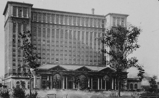
In the photo, the carriage house is to the left with the Trolley Stops on the right. A few cars can be seen in the front of the building.
Coincident with the station opening, Ford Motor Company produced 200,000 cars that year. More importantly, Ford raised the worker’s wages to $5.00 per day, which is double the previous rate. This was done to lower the turnover rate among the factory workers, and to boost the wage to allow the workers to purchase the cars that they produced.
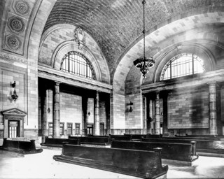
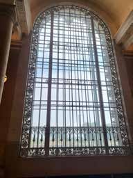
The station serviced the New York Central, Baltimore & Ohio, and Canadian Pacific Railway. At the beginning of World War I, more than 200 trains left the station each day. In 1920, Detroit was the 4th largest city in America, and Ford produced one million cars per year. Pushing forward to the 1940’s, more than 4,000 passengers used the station per day, and more than 3,000 people worked in the office tower’s 500 offices. The upper floors were never finished. We walked through the station plan, highlighting the major functions of the areas. This was a large station and had a number of amenities. There was a dining room, café, lunch counter, barber shop, men’s waiting room (reading room), women’s waiting room, parcel counter, ticketing office, drug store, tobacco shop, telegraph office, news counter, and information counter. The general waiting room was a large open area with passenger benches. The area was ringed with arched windows guarded by decorative iron grids. The windows could be opened for ventilation. The chandeliers were suspended from the arched tile ceiling.
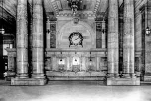
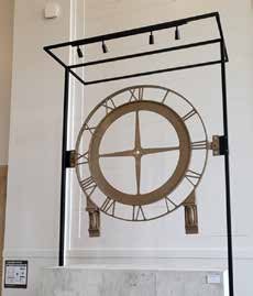
The ticket office had a number of service windows, but some were obscure and did not have large queue space. The clock was stolen and was a major restoration effort.
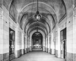
The arcade area was the location of many of the shops and amenities. The photographs show the station devoid of passengers but one can visualize the hustle and bustle of the station. The marble floors still exhibit grooves from the baggage and freight carts.
On the timeline of the station, it fell on hard times. The New York Central attempted to sell the facility for $5 Million in 1956. The 1960’s saw the railroads move operations out or end passenger train service. This culminated in the segmented operations of the Penn Central in 1968. Then we moved into the Amtrak era starting in 1971. In 1975, the main entrance and waiting room were reopened. The Station was declared a Historic Landmark. The last train left the station in 1988 after 75 years’ operation.
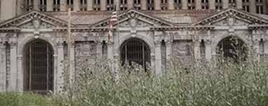
This marks the beginning of three decades of abandonment. Many projects for the site were proposed but nothing was started. The ruins of the station were used for four movies. The building was stripped of valuable material and the remains were vandalized. The largest factor of deterioration was the loss of the windows throughout the structure allowing the elements to enter and do their work. The station became symbolic of the decline of Detroit.
In 2008, a video was made of the condition of the station. The video can be found at: https://www.youtube.com/watch?v=T_ahHIqxkaU. This video contains a large number of views of the station’s deterioration prior to the restoration activities. The video is dark and disturbing. Waste, debris, and vandalism is widespread.
The station building entered a new phase in 2018. Ford invested in the building to create an innovation hub for future transportation. The station was purchased for $90 million. Over the next 6 years, Ford hired 3000 tradespeople to renovate the station and the surrounding area. The estimated cost of the renovation was $740 million, but in true remodeling fashion, the cost escalated to $950 million. The work included pumping water out for 2 years. The basement held 3.5 million gallons of water. The moisture delayed the work but kept some areas intact. 4000 cubic yards of debris was removed revealing 1000 holes in the floor. All of the windows had been shattered. The stabilization work on the foundation required hundreds of truckloads of concrete. The steel hidden in the walls needed to be replaced. The consensus was that many more years of decay would have made the building unrestorable.
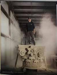
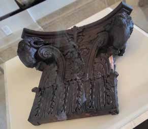
The pillars and capitals were crumbling and needed to be replaced. The Indiana quarry used for construction closed in 1988. Ford reopened the quarry and built a new haul road. Leftover blocks of limestone were found in the quarry. The existing capitals were crumbling. They had intricate adornment which was not intact on any of the capitals.
Several of the capitals were scanned and the images merged in the hope that a CNC machine could carve replacement capitals. The machine crashed as the images were too complex. They located an expert stone cutter, John Goodrow, Sr.. He carved a replacement capital in 428 hours from a 21,000 pound block into a resulting 11.500 pound capital. The hand carved capital was used as a CNC pattern to carve the remaining capitals.
This is a photo of the restored building facing with the capitals and replacement column in place. In order to finish many of the interior details, a call went out for historic relics to the community. This resulted in fountains, finials, mail chutes, and light fixtures returned to aid in fabricating faithful restorations. All 29,000 ceiling tiles were checked and in the end 8.7 miles of grout was required. Only 1300 tiles needed to be replaced.
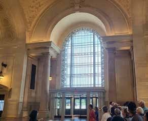
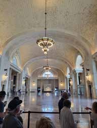
The main entry is a striking example of the completed work. The dining room is still being restored but currently houses displays of the artifacts.
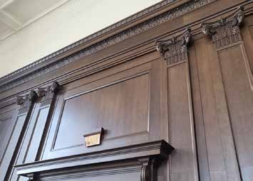
This is a rams head finial from the men’s smoking room. None of the originals remained in the building but an anonymous loan returned one. This was used to create plaster casts to return the adornment to the room. The next photo shows the finials in place within the paneled room. In an interesting development, a note was found in a beer bottle behind a cornice high on the wall. It was dated July 1913.
One item of the carriage house exterior was a central clock. The clock was missing and after requests went out, an anonyous donor directed the salvage crew to the clock’s location. It was recovered and will be reinstalled as the work on the carriage house is completed. The carriage house is to be repurposed as a restaurant.
Within the main hall, the marble floors were discovered to be undamaged. The floors were cleaned and are now in service. The chandeliers were all missing and needed to be recreated from drawings and photographs.
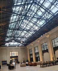
The concourse area was roofed with exposed copper panels in the original design. This left the area rather dark. The decision was made to utilize glass panels as the roof sheahing to brighten the area. There are furnishings in the area for the office occupants to use. This facility is open with business offices. The spaces are used for those occupants. The facility may be toured on a scheduled basis.
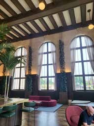
The womens waiting room is fully restored with colorful furnishings. It is a bright and open space. Again this is an area available to the business occupants. Other areas of the building display the deteriorated conditions encountered. The ticket window area was recreated including the clock. This clock was recreated from a small iron fragment returned to the building. It is now in place. The ticketing area is now a gift shop but the ticket windows were rebuilt and stand as the wall. The waiting area windows were framed with iron railing and these items were all gone. The decorative iron work was recreated and installed to frame the windows.
The building was reopened to the public in June 2024. This is an amazing journey for a historic structure repurposed and restored for Detroit. The building currently houses 120 businesses with the main focus on mobility, energy, and multimodal logistics. The station is visited each Christmas season by the CPKC Christmas Train. This is a lighted holiday train that visits many of the cities along the historic routes of the Canadian Pacific and Kansas City Southern.
Clinics for 2025
November Clinic – November 17, 2025
Maritime Railroading, History and Modeling Opportunities
Gerry Glancy Biography

November’s clinic will cover the wide variety of ways that the railroads, in times past, interfaced with oceans, lakes, and rivers. The clinic will then segue into modeling techniques. Current modeling resources will be utilized to show how the Dueling Gauges & Navigation Company was constructed with extensive HO scale maritime operations. Modeled on San Francisco’s Embarcadero, kit bashing and scratch building techniques were used to depict piers, transit sheds with bulkhead buildings, car floats (ATSF) and car ferries (WP’s Las Plumas). Ships and lighters are also described. Lighters are the large usually flat-bottomed barges used especially in unloading or loading ships. There is even part of the story of interest to Narrow Gaugers, indeed all gaugers!
Gerry Glancy’s Non-Railroad Biography
Born, raised and educated in California, fortunately in an era when public schools were of high quality and enjoyed wide public support. He graduated from medical school in 1966 at which time (Viet Nam) a special set of laws covered physicians. The vast majority of new grads faced a two-year military commitment in some form or other. So, Gerry signed up for two years to “get it over with”. Fourteen years of active duty later he was still getting it over with. It was actually the US Army that sponsored his training in pediatric orthopedic surgery. Finally, deciding geography was more important than furthering my military career I settled in Denver and joined the staff at The Children’s Hospital. Ironically, I retired from the same location that I trained in orthopedics, Fitzsimons. Now watching 7 grandkids grow up with the satisfaction of knowing that I’m able to facilitate some of their adventures, including model railroading.
Gerry Glancy gave us insights into the melding of railroads and maritime operations. Early on railroads learned that trains do not float. This meant that any water crossings needed to be aided by other means. In modern times ships are huge and cargo containerized. The ships carry many railroad trains of freight and give rise to long strings of double stacked containers. This is problematic for modelers as most do not have the space to add the scale container ship model and the length of trains necessary to reflect modern realities. This could be the end of the story, but earlier railroad and maritime interfaces were more interesting.
As soon as railroads materialized, the lines headed to the shores and docks. The golden age of railroad/maritime operations was from 1880 – 1980. This era was marked by inefficient, labor intensive operations. During this period, few changes or improvements were made. The method of operations got the job done. For model railroaders the period gave them excellent modeling and operational opportunities.
What is the attraction of modeling? The dockside trackwork is intricate with tight curves and small locomotives. The setting is a gritty, grimy industrial setting. Like the small locomotives, a Varney kit for a B&O dockside switcher was available. The instructions were rudimentary, and the kit was not well finished out of the box. This gave any number of modelers their start in modeling dockside switching and modeling.
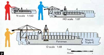
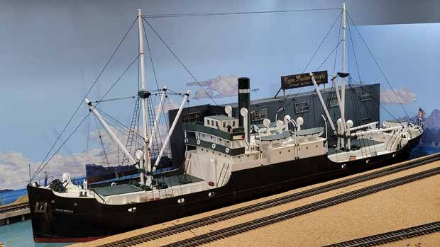
The generic elements of railroad maritime modeling include ships, lighters, tugs, railroad piers, and car floats. The cargo ships in the golden age of operations evolved over the years. The ships were originally sail powered, and later sail/steam powered. Then we gave up on sails and went with steam power for the mobility. Finally, at the end of the golden era the ships were powered by diesel. As this was happening, the ships increased in length from around 300 feet to 600 feet. For example, the “Yakina Bay” ship model at the Colorado Model Railroad Museum is a 490-foot-long ship that scales to about six feet in HO scale. This size is a deterrent to modeling maritime operations for most people.
The diagram gives an example to the lengths of model ships in various scales. Ore dock operations are very problematic as the docks and the ships are very large and even an attempt at modeling requires a great deal of compromise to offer a model scene. There are opportunities to build a model maritime scene using Sylvan scale model ships by modifying and adding details to mimic the freighter for your chosen locale.
Glenn Runkewich built this model for his model railroad as a modified coastal freighter. The modeler will need to spend some time to find the appropriate starting point for their ship model.
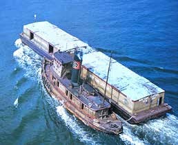
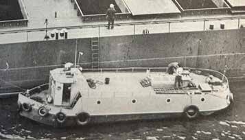
The other question that needs to be answered is do you need a ship model? During the break bulk era of maritime trade, ships were not necessarily docked, but cargo was transferred to lighters and then off loaded at docks. Lighters were smaller vessels that could receive freight from ships in the instance where ships could not approach the dock or needed a lighter load to safely approach the dock. Lighter models can be found. These appear to be barge-like in configuration. Another boat servicing the ship is the bum boat. This is a crew supply boat, which could be thought of as a general store on the water.
Essential to the efforts were tugboats. These changed within the era moving from steam power to diesel and from sidewheelers to propeller driven craft. Some of these boats were owned and operated by railroads. They were painted with the railroad’s signature color schemes.
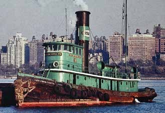
The tugs needed fuel and fresh water, and these were provided at dockside facilities for them. The tug boats were used to move car floats on the waterways and into dock positions. The use of car floats began in the Civil War and quickly evolved to speed the loading and unloading process. The car floats are a series of tracks on a bargelike boat.
They can be powered, but most often were an unpowered craft. The tracks run bow to stern. The piers for these floats were specialized with a movable apron to meet the float tracks with a gantry to position the apron. There were projections into the waterway that were termed dolphins to guide the float into position. The docking of a float was quite tricky and involved positioning the float against the dock at the apron edge and locking the float to the apron with a series of pins or a single kingpost. Unloading a float was a serious operation as the car weights needed to be accurate to allow unloading to proceed with minimal side to side displacement of the float.
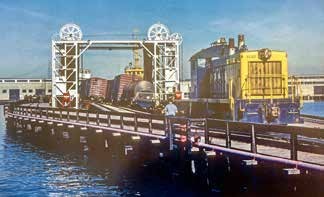
Luckily for HO scale modelers, Walthers has produced a number of kits to model these operations. These are a car float, a float apron, and the pier terminal building. The car float and float apron are available from Walthers. The pier terminal building has been discontinued but is still available on eBay or other aftermarket sellers. Gerry has used wood pins to secure his model car float to the apron. He rolls the car float up to the dock, gets the apron and float into position, and finally affixes the two together with four square wood pins.
The poster child of maritime railroad operations is New York City during the prime era. The New York City area boasted 11 Class 1 railroads, 5 beltline railroads, and handled 3000 cars per day. The car float traffic was in competition with ship movements, passenger liners, and passenger ferries in the Hudson and East Rivers.
The railroads themselves had passenger ferries.
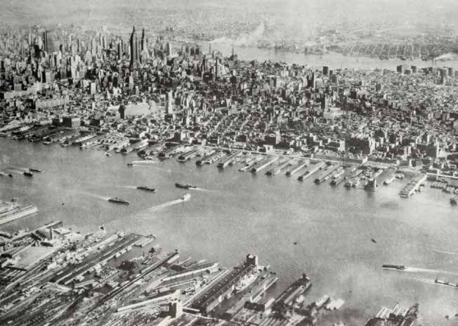
The car ferries were standardized so they could be loaded and unloaded at any car dock. The harbor had an unusual car float called a platform car where the float had two outside tracks and the center area was a car height platform. The platform was car door height and allowed loading and unloading of the cars while under way. Lighters in the area were covered, and some were heated or cooled to handle more sensitive cargo. Bulk commodities were handled in the harbor including export coal. Large McMeyler unloaders were available to handle the bulk commodity trade. Grain Elevators were found dockside to store export grain. An unusual boat in the harbor was a floating grain elevator. This was used to unload grain ships into lighters along the docks. The tugboat fleets were painted with railroad colors similar to the diesel paint schemes. In that fashion, it was easy to recognize the railroad’s tugs.
Moving toward the rivers that the railroads encountered going west, one would think that these would be bridged. Not really, as the river channels were wide and subject to seasonal flooding, it made sense to span the rivers with car floats and tugs. For example, the Southern Pacific Railroad moved trains from the Sacramento area to Oakland/San Francisco on the Solano, a rail ferry. This operated until 1930 when the Carquinez Strait Bridge was completed. Again, the railroad was faced with a wide crossing near New Orleans. The railroad used car floats and tugs to make the crossing until the Huey Long Bridge was completed in 1935. Aside from the major crossings, there were still car floats and tugs used on the Mississippi River into the 1970’s.
Along the northern U.S. border, the Great Lakes offer new and different challenges for railroad maritime traffic. The freshwater lakes have a number of drawbacks to ship activities. The fresh water density is less, the waves may be more severe, and the ice formation is at a lower temperature. This all results in the need for larger and more substantial car ferries. As these were larger there was an opportunity to add passenger service and automobile service to the Great Lakes routes. This all adds to the revenue stream for the operations. A unique feature of these operations was that the rail cars were jacked up to stabilize them during the crossing. The stern loaded ferries were equipped with a stern apron to divert water from entering the vessel. Ice along the shore was problematic, stopping the ferries off shore. Loading the ferries was subject to the same problems as all railroad/ship interaction. The loads needed to be balanced side to side as the loading/unloading happened.
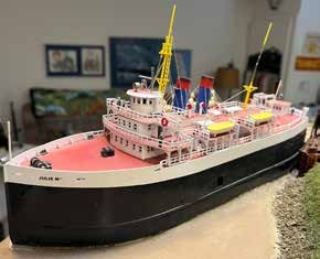
Modeling these ferries is not helped by Walthers, so an article in Model Railroader, April 1975, had plans to model a Great Lakes ferry. Pat Lana built the “Julie M” as his version of the ferry. The model is detailed with rigging in N scale on his CRANDIC Route Railroad. Extending the car ferry story into Nova Scotia, all rail freight came in by ferry. The difficulty is that the trackage in Nova Scotia is narrow gauge and the standard box cars coming in are standard gauge. The railroad simply dropped the standard gauge trucks and ran the cars on narrow gauge trucks on the island. The process was reversed to return the cars to the mainland.
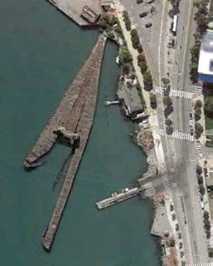
Pete Doty built his version of the Seattle waterfront. This was scratch built. Gerry Glancy is building his rendition of the Embarcadero in San Francisco. He built the Pier #35 using the Walthers kit for the Pier Terminal Building adding parts from the Bailey Saving and Loan. The tracks entered the central arch but quickly exited to the side along the wharf. The rails are embedded into the street track inserts from Walthers which gives a nice, finished appearance to the base.
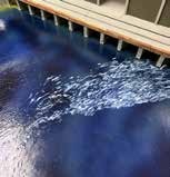
The pier pilings were modeled with ¼ inch square styrene shapes. The water was finished with Mod Podge to add ripples and waves in the area. The final building is very convincing as a rail served pier structure. The Santa Fe tugs were prevalent in the Bay and were equipped with fire monitors. This is simply a water cannon designed to assist in fire suppression. They stayed in service until the 1980’s. Part of the modeling effort included ATSF China Basin dock. To help with the variety in railroads in the Bay area, the Western Pacific Pier 43 was modeled and has been recently updated with piers and planking. There is the beginnings of the narrow gauge car float and dock in the area. Las Plumas was the Western Pacific diesel powered car ferry equipped with a new at the time bow thruster to facilitate movements. The one historic photo has the Royal Scotsman locomotive in the ferry.
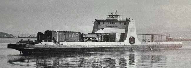
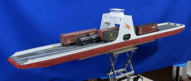
Gerry’s model of Las Plumas follows the lines carefully with the superstructure emblazed with the Feather River Western Pacific logo.
Other maritime railroading includes the Sea Train. This was a special ship equipped with four decks and could carry 80-90 40-foot cars loaded by crane into the decks. The route was from New York to Florida and on into Mexico and even Cuba. When the Cuba trade was stopped, the line struggled along finally going out of business.
The barge line to Whittier, Alaska has a specially equipped barge with the lower deck for railroad cars and a superstructure that will support other cargo. This includes containers, small boats, and other equipment for the area.
While modelers may not think they have room for maritime operations, a small corner layout could suffice. Or maybe just the slope to the waterway on the layout equipped with track to a small dock and car float to satisfy that special rail customer on the layout.
As an extension to a layout, a small narrow-gauge line, Wiscasset, Waterville, & Farmington could add interest to an area. This was a 2-foot gauge line interchanging with Maine Central. A fun flight of fancy.
Vashon Island, Washington has no railroad but was served by a car float anchored at a dock to receive strawberries. When the cars were filled, the railroad retrieved the car float and replaced it or held off to the next harvest season.
The end of the maritime operations was a slow wind down. The Great Lakes car ferries were converted to other uses or scrapped. Early container operations did not start with oversize ships, but rather converted freighters with a smaller profile. Sylvan models have a smaller container ship, Manchester Liners, which can stand in for your chosen ship line.
This was an interesting look at the railroad/water interface. This gives a good starting point for those interested in the maritime operations.
October Clinic – October 20, 2025
What Happens To Your Model Layout & Trains When You Are Gone? The effects of planning for the inevitable, or not . . . . .
Richard Frazier Biography
Richard Frazier is originally from Oklahoma where he obtained his degrees in Computer Science and Computer Architecture from Tulsa Junior College, Langston University, and Oklahoma State. Helped deploy the largest UNIX application outside of the Federal Government in the early 80’s, worked for a variety of technology firms Anheuser-Busch, MAPCO, Sabre, Oracle, and Konica-Minolta. Also, he worked in the model train industry at InterMountain Railway. Now in Colorado, he works in the Financial Services industry as a Sr. Financial Advisor, supporting clients around the country, and in his spare time operates YardSaleTrains.com and works for his wife in their woodworking business.
We all know that the day is coming when we will be gone. Over the years of our modeling ‘career/hobby’ we will have obtained…….several items. What is going to happen with them? What do you want to happen to them? Learn from someone that has seen what can happen – some good, some not so good – and how you can plan for it. Find out how it can make it much easier for those left behind that have to deal with your collections & layout.
Richard began the clinic with a few axioms on what all model train enthusiasts have in common:
- N scale is the best scale ever!
- Santa Fe is the best railroad to have ever existed.
- They think “Ready to Run” is evil.
- Actually, all we have in common is that we are getting older.
The items to cover in the presentation include: harsh realities, what is the impact of not planning, what is the impact of planning, what is going to happen is not what you think – get over it, and what should be the desired outcome.
The first element in planning for your model train layout removal is what to do with a layout. It is nearly impossible to sell an entire train layout as this is your vision and has been mapped and constructed into your available space. Finding someone that shares your vision with a similar space is impossible. This leads to the conclusion that the layout will be trashed. The first thing which needs to be planned is how the layout is disassembled. Plan for a disassembly activity. There are two parts to this.
Plan for the process and communicate the process. Just because you know how it comes apart, no one else can share that vision without your planning document. Share in documentation the tools needed to break down the layout and the disassembly points. Did you bolt the sections together and then forget where the connections are? This is the starting point for your layout notebook. The first section should cover the layout process. The notebook should be located near the layout and readily visible. Don’t hide this on a bookshelf with the rest of the railroad manuals. An important part of the planning process is the deposition of the layout parts. Are there friends, acquaintances, and family that would appreciate a portion of the layout? Record their requests into the notebook in the layout section so that the layout can be carved up to retain their requests.
Include a section on the electronics in the notebook. Locate the electronics, power, and layout controls in the notebook with a detailed description. These items hold some value and can easily be destroyed as the layout is removed.
The layout needs to be stripped of the removable materials. The buildings, figures, signs, trees, and other material that can be reused should be removed and stored for disposition. Remember again that someone of your acquaintance may have need of the material. Track may be detached from the layout and can be reused. Of great value are the turnouts if they can be cleaned and are still operational. The modeler should communicate to their survivors the dramatic differences after the layout removal process. This will be a quick and noisy end to the hobby of the modeler. The layout is just the start of the model railroad deposition. There are several categories of material that will need attention.
There are more sections to the notebook:
- Engines
- Rolling Stock
- Structures and Scenery
- Electronics
- Books and Memorabilia
- Photographs and Videos
Locomotives are an area of the greatest value in the modeler’s realm. These are valuable to other model railroaders particularly if they are brass or brass hybrid models. Some may hold emotional value due to age or previous ownership. The inventory within the notebook should denote the specifications of the item. List DCC, sound, keep alive, unique qualities, and other value-added information. Keep the locomotive boxes in a labeled container with information on decoders in the individual box. List specific bequests in the inventory to direct the piece to the named recipient.
Rolling stock is the largest category of material with the lowest value. Again, an inventory is necessary with boxes and notations on unique features of the car. This is where some collections of cars can retain greater value if it is noted on the inventory. Did you get a consist of a named passenger train with the locomotives? Add that information to the inventory. Did you collect a series of cars that denotes a particular railroad’s billboard cars? Put that information in the inventory, so it can be listed as a set. Again, list specific bequests in the inventory to direct the pieces to the named recipient.
Structures and scenery are the most awkward to successfully retain. These are difficult for non-modelers to deal with. The structures and scenes around the structures may be desired by members of your train group. Try to accommodate requests for these items and list them in the notebook. Some scenes may be removed intact and will add enjoyment to others’ layouts. Add notations in the notebook as to how the item was attached to the layout and can be successfully removed. Partially used scenery items like ground foam, glues, paints, ballast, and other materials can be donated to assist others in developing their layouts. Choose a recipient and note that in the notebook.
Electronics is a separate section of the notebook. The location was touched on in the layout portion, but this section should be more specific on the DCC system and additional components that are installed within the layout. Be certain to include track detection, working animation from signals, tortoise switch motors, Arduino, Raspberry Pi, and short circuit protection. Basically, list anything that turns on and has indicator lamps. These items can be quite valuable and can easily be destroyed by aggressive layout removal.
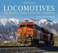
Books and other memorabilia that you have collected over the years will need to be distributed. Magazines are a small part of this collection and generally have no value. Most issues are available online and the more recent issues have retained little value. Books on the other hand can be valuable, particularly early editions and autographed books. Again, you will need to create a list of books with annotations on the special characteristics of the edition. If you have destinations for these items, be certain to add that to the list and place this in the notebook. If you have a large collection, it may be helpful to use software to build your library list. One application, www.librarything.com, is free and allows you to keep a listing on your phone. This prevents the duplicate purchase of a book. Railroad memorabilia is a large and varied category. This includes lanterns, plaques, builder plates, signs, artwork, paperwork, railroad China, promotional materials, nails, switch stands, spikes, rail, timetables, and other railroad items. This is very hard to value as the items may be the stuff only you would want or items that have large following and would command high prices. If you wish to research books and pricing refer to https://www.alibris.com/ . This site is a collection of hundreds of book sellers.
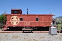
Another visual category are your photographs and videos. Digital photographs are a curse as the number of photos dramatically increased as the world went digital. This is a lot of stuff to describe and catalog. Here is another use of the notebook. Add in the description of the visual arts that are available in your collection. Be certain that the password of the storage device is available to others. Add in the description as to where, when and how this was acquired. Is the collection all yours or does some of it come from others? Understanding the value of the images comes about from the rarity of some photographs. An example of this is the BNSF 489357 Great Northern heritage hopper car. This special car was on the rails for about eight days prior to a wreck where it was abandoned off the right of way. Some railroad fan could have a good photo of this car on the rails in use for the eight days. Your documentation of last day’s events is of great value.
Now that you have gathered all the railroad item information together, you need to plan for the ultimate end disposition. What do you what to happen? Don’t set your heirs up with unrealistic expectations. This is all an emotional burden. The success of this effort after you are gone depends on the notebook and the organization of the information. Be very clear on what you wish to happen and if possible designate individual or organization to take charge of this effort.
Find a path to gain some value from your investment. Donate the collection or parts to worthy causes. Sell the material on eBay with the usual pros and cons. Sell on Facebook marketplace. This may have a larger audience but with some downsides. May want to haggle over price, will need to meet in person, and may be inexpensive to sell. You may also sell it on Auctionninja. This has a very large presence, and you can list 100 to 400 items. You will need help on pickup day. One can organize a Model Train Garage Sale. This is more focused for the local model market and can benefit the local modelers that may have known the modeler. You will need to take credit cards. As an alternative, sell the inventory at a train show. This carries the same requirement as a garage sale. You will need to take credit cards, and some locales require sales tax to be collected. You may sell to a broker, dealer or reseller. This can be a one-shot deal if the inventory is right for the buyer.
Some scales and items are special cases and proceed differently. G scale outdoor layouts generally are part of the real estate sale with other items as listed above. O scale material is of two categories. The pre-war items are special cases and would be valued on the collectors’ market. Post war items need to be dealt with as noted above. Tin plate items and standard gauge material will again be valued by the collectors’ market as a niche sale.
A club can aid the seller or owner to advise on a strategy. All clubs should have an estate coordinator, Club member volunteers can assist with the inventory, pricing, and path forward to moving the merchandise.
September Clinic – September 15, 2025
The Aberdeen and Rockfish Short Line
Kevin Ruble Biography

Kevin Ruble is a fourth-generation rail professional, having started his railroad career immediately after college as a management trainee, and subsequently Assistant Manager – Car Service for the Missouri-Kansas-Texas Railroad (better known as the Katy) in Denison and Dallas, Texas. After graduate school, Kevin served as a strategic consultant for over 85 short line rail transactions over the span of 25 years, culminating in the acquisition of a 126-mile CSX branch line in Michigan, from which Marquette Rail was formed in 2005. Kevin was Marquette’s Founder, Managing Member and CEO prior to the railroad being sold to RailAmerica (and ultimately Genesee & Wyoming) in 2012. A few years after moving to Colorado, he acquired the remaining assets of Caboose Hobbies in 2016, after that iconic store closed, and moved the store to Lakewood, where it operated until closing with the COVID pandemic at the end of 2020, but let’s not dwell on that sad story. Since this past February, Kevin serves as CEO of Transcendence Project PBC, a tech startup in the artificial intelligence space.
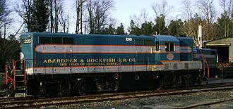
In this clinic, we will take a look at the Aberdeen & Rockfish, a 46-mile railroad in North Carolina that in many ways is a typical southern shortline, and in yet other ways an enigma. Model Railroader magazine recognized A&R as a “Railroad you can model” in its November, 1965 issue, an article that captured Kevin’s attention then and still today.
Kevin Ruble presented his motivation and plans for a model railroad depicting the Aberdeen and Rockfish Railroad. His interest in this railroad was first noted in a Model Railroader article in November 1965. It was note in the article that the A&R was a railroad you could model. This family owned short line railroad had a number of quirky things that have persisted into modern times.
The road of personal service is exemplified by a couple of examples. The rail crew in 1938 waited for a boxcar of watermelons to be loaded in Raeford. The only requirement for this delay was that the engineer and fireman could borrow the farmers car to go fishing. By the time they returned, the boxcar was loaded and ready to continue the journey down the line. In another instance, the conductor of a motorcar was directed to match a piece of ribbon to fabric at Capital Department Store in Fayetteville. He of course delivered to the customer “The
Road of Personal Service.”
The railroad was formed in 1892 by John Blue to support his lumber and turpentine business. Part of the support for the line came from the Seaboard Air Line to provide access to Fayetteville, a stronghold of arch rival Atlantic Coast Line. It is a 47 mile railroad connecting the Seaboard Air Line, Atlantic Coast Line, Norfolk and Southern, Cape Fear Railways, and Laurinburg & Southern Railroad, within North Carolina. The railroad is still owned by the Blue family. The northern portion of the railroad from Aberdeen to Raeford is built in the sand hills virtually on the ground with minimal grading. This portion is basically a logging railroad in construction with a 2.5% grade from Aberdeen to the top of Blue’s wye. In keeping with the frugal nature of the railroad, the line was constructed with 56 pound rail, and this is still the rail weight today.
Continuing east from Raeford toward Fayetteville, the grades are more gentle but still curvilinear. This was the subject of a conversation with Fort Bragg officials and the Blue family during WWII on whether the line was in danger of being hit by bombers. The majority of the line was constructed from 1892 to 1912. Some of the eastern portion of the line was constructed using convict labor and bond funds. In 1934, the line was extended tothe Fayetteville river terminal which included an oil loading terminal. This oil terminal handled aviation fuel for Fort Bragg. The river terminal greatly expanded during the 1950’s and 1960’s with a large number of major customers establishing facilities in the area. At the present time the river terminal resembles a Class One railroad facility. The list of customers for today’s A&R include the following:
- Aberdeen: No major customers
- Ashley Heights: Geigy Chemical, Koppers
- McCain/Sanatorium: North Carolina State Hospital
- Raeford: Burlington Industries, Upchurch Milling, Hoke Oil Co., Farm Center, Inc., Laurinburg & Southern Railroad Interchange
- Skibo: Cape Fear Railway Interchange
- Fayetteville: Borden Chemical, Gulf Oil Co., Esso Standard Oil Co., Cape Fear Feed Ingredients, Swift & Co., Cohen & Green Salvage, Fayetteville Bonded Warehouse, ACL & NS Interchange
- Elsewhere: Pulpwood, sand, and agricultural products
During World War II, the rail line was swamped with traffic handling not only war material but passenger trains of soldiers to and from Fort Bragg. Unfortunately, the long standing operating schedule was for four trains per day, except Sunday. Basically, these were turn jobs with #22 leaving Aberdeen at 8:00am and reaching Fayetteville at 9:45am. The train returned as #21 after 3:30pm. The Aberdeen to Raeford local, #41, left before 9:00am and returned as #38 after 4:30pm. In the mid 1960’s, Aberdeen featured 21 Seaboard Air Lines Railroad trains per day, 12 passenger and 9 freights. Fayetteville, also had 21 trains per day. Both towns were branch terminals for the original Norfolk Southern.
The A&R today operates on the eastern portion of the railroad. There are a large number of covered hoppers stored on the main line between Raeford and Timberland effectively dividing the railroad in half. It operates as a switching railroad in Fayetteville.
At this point of the presentation, Kevin presented his model railroad plans. Actually, this was two separate plan ideas. His design was for a 2400 square foot basement, but he currently has a “second” bedroom for the layout.
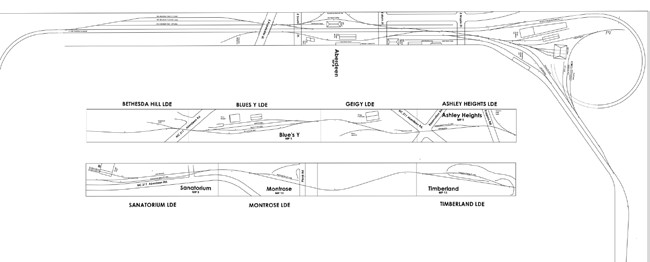
The layout design elements are shown in the illustrations with the final apartment sized plan as the last illustration. The full basement plans include all the areas served by the A&R with the abbreviated apartment plan holding the major areas. This flexibility allows the railroad to come to life as Kevin’s life continues to evolve.
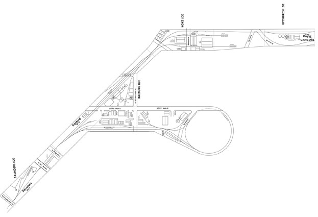
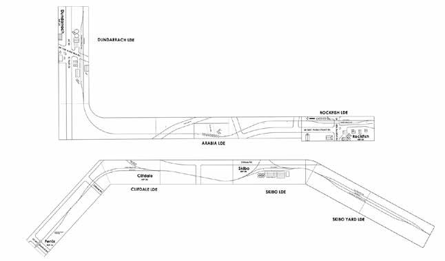
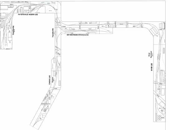
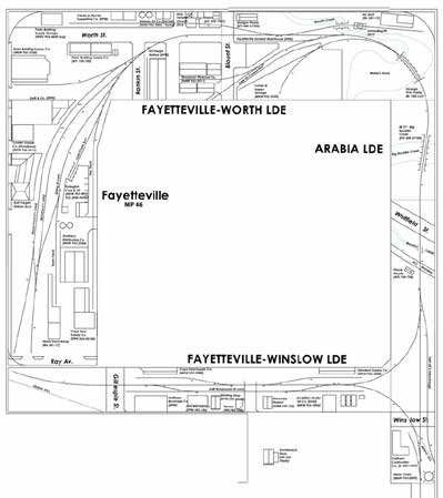
One of the modules for this construction was completed and brought into the meeting. The rest of the modules will be completed along the same lines to build out the layout. Kevin was fortunate that Athearn made an A&R boxcar. He located a couple of cabooses that could be stand-ins for the A&R caboose. The models do not include the side door. Atlas made a couple of locomotives for the A&R. All of these are HO scale models.
Operations in Aberdeen occur as they always have with the engine and caboose starting from the Aberdeen shops. The combination moves down the line and into CSX territory crossing the double track main line to the South Aberdeen yard. They pickup the day’s transfer cars and move back through the connection to the A&R track continuing to Fayetteville or as the local to points intermediate. This action has been trucated in recent times as the through line is currently blocked by stored covered hoppers. It seems as if there are a larger number of stored hopper cars throughout the rail system, and one wonders if they will be used in the future. The local was usually powered by the A&R F3A unit. Starting in 1958, the A&R and LRS combined to get a unit coal train routed on their lines to the power plant at Wilmington. This old move was to compensate for the power business generated on their lines. The deliveries were made faster using this bypass as the loads did not need to pass through the Hamlet yard. This arrangement lasted until 1980, and the railroads were compensated for the loss in revenue for an additional five (5) years.
The traditional rail passenger service through the line was discontinued in 1921. The passenger and mail service was provided by Jitneys. These motor cars were called Doodlebugs on other railroads. This was a combination passenger, mail, and freight self-powered unit.
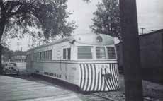
The A&R was an early adopter of diesel power. Unit 200, an F3A was purchased new in 1947. The following year, unit 201, another F3A locomotive was purchased. Unit 201 was deemed unsuitable for switching duties and was sold when the railroad bought the GP7, numbered 205. Unit 200 was traded in on a GP18, numbered 300. Later, a GP38, numbered 400, was purchased in 1968. As the A&R grew, the locomotive fleet expanded with the addition of another GP38, numbered 405. The fleet was further expanded with the addition of an NW2, an SW9, another GP7, and two CF7s. An important spotting feature of the A&R diesels is the small size of the fuel tanks. The short mileage nature of the line did not require larger tanks.
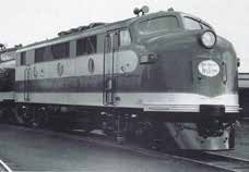
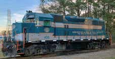
A historic Mikado (2-8-2) numbered 40 was stored at the engine house until sold in 1977 to the Valley Railroad in Connecticut. It still operates today on that line. A 1935 Chevy was made into an inspection car for the railroad, numbered 105. As they used limited amounts of diesel fuel, a tank car was stationed at Aberdeen with regular trips to the Gulf Oil terminal at the River Port.
The caboose fleet for the railroad was unusual as all the cars were equipped with side doors for parcel freight. The cabooses were home built or inherited from the Seaboard Coast Line, so they followed the SCL profile but with the added doors.
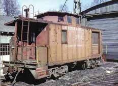
The real estate was interesting typical short line structures. The headquarters is located in a two story building in Aberdeen with some modernization. The bay windows in the front were removed and an antebellum entrance added. The doors to the side were replaced.
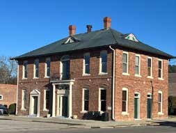
The Aberdeen Union Station has been well maintained and currently houses the Aberdeen and Rockfish Railroad Company artifacts and memorabilia and other local historical items. The Aberdeen shops have been modified over the years, with an addition in front of the shop building and a change in the roof line on the brick structure. To enter the shop area there was a three way stub switch which was replaced in 2015 or so.
Historic McCain, formerly Sanatorium was the location of the rail served power plant and the highest point on the railroad. It was said that it was a good place to grow peaches as it never had frost. This is the location of the former North Carolina State Hospital which is abandoned with a spooky exterior.
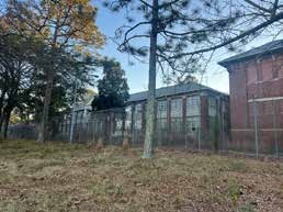
The presentation included additional connecting lines and branch lines to the A&R. As illustrated in the photos, a lot of change has occurred along the line with business changing and disappearing.
The question that is stilll unanswered as to the era that will be modeled. Kevin is thinking the 1960’s, so he can run the F3 unit and the GP38. This era may morph as the layout grows from the apartment size pike to the basement size operation. This also entered into the track planning as the essence of the railroad is maintained in the apartment with the omission of the River Terminal. The track plan was further modified as the inventory of switches was heavy on #6 switches and light on #5 switches.
August Clinic – August 18, 2025
Creating Your Own Photo Backdrops
Rich Gibson Biography
Rich grew up in suburbia on the east side of Cleveland, Ohio and became fascinated by rocks and minerals at an early age. In 7th grade, Rich thought it a good idea to correct his science teacher’s geology errors …. it wasn’t. Rich attended Allegheny College, majoring in Geology, and followed this up by earning an MS and PhD at Virginia Tech. Despite always wanting to pursue an academic career, there were very few positions available when he graduated. Thus, Rich ended up joining Amoco and worked for them, and their successor BP, for 21 years on oil and gas exploration and production projects in numerous parts of the world. His early retirement in 2010 lasted 2 weeks before he joined Apache. 3½ years later joined SM Energy where he retired in 2023. He and his wife (Janet) tried to get located in Denver in the early 1990’s, but took a rather circuitous route, moving 8 times and finally ending up here in 2016. He has always had a general interest in history and enjoyed traveling and hiking. However, Rich’s activities over the last ten years have become increasingly rail related.
Superindent Rich will present his methods of creating photo backdrops for a layout or diorama. Rich has become very skilled at manipulating photos. He makes backdrops from Google Earth images, his own photography, and mixes and matches the images to back date the photo to the 1950’s. As one can imagine, the contemporary photos contain buildings and vehicles not appropriate for the 1950-time frame. The resultant image is printed on large scale paper that can be adhered to the backdrop substrate.
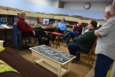
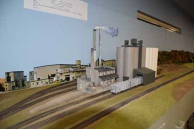
Background Buildings on the Backdrop
This is the outline of the presentation:
- Equipment and timing considerations
- Photography tips
- Laying things out
- Photo editing
- Printing and installation
- A real-time Colorado example
To begin the process, one needs to have a vision of what you want. If you are familiar with the area that you model, you can more easily translate that into photographs that depict the area. The equipment for this project is relatively simple. Rich uses his phone camera to grab the photos. While a higher end camera may give greater resolution for the photos, it is not really necessary. As will be pointed out later, there is a good deal of post processing to this endeavor, and ultimately, the printed photo backdrop is at a fairly low resolution. One will need a computer with basic photo manipulation software. The first software need is presentation software such as PowerPoint, or Keynote. To further process the photos, one will need photoediting software such as GIMP, Photoshop elements, or Photoshop. GIMP can be downloaded at: https://www.gimp.org/. The process will need access to Google Earth and the internet. This process will take patience as there is a bit of trial and error to developing the end result. There are two options for timing of the backdrop work. Either the backdrop before or after the installation of the foreground. Installing the backdrop before the topography allows one to shape the scenery to match the backdrop. The installation after the topography requires that the photos be cropped and adjusted to match the installed shapes. The roads, rivers and other fixed scenery objects will need to be adjusted and shaped to match the existing terrain. In any case, install the backdrop before you add any scenery, buildings, or other fixed elements.
To create your backdrops, you need to take many photos of the area that you model. Rich does not recommend shooting a panorama. As you stitch the photos together you will end up with an arc as the elements are matched. This can be corrected in the photo processing software but will add an element of distortion. His recommendation is to shoot photos along the rail line at about the rail elevation. These photos can be more easily stitched into a convincing diorama. Photos should be shot with about a 1/3 overlap between photos. This minimizes the distortion at the photo edge. Focus the photos on distance objects, not the foreground. Be certain to take photos along roads and further along water crossings as these will be very useful in the later process. The result of all these elements is to provide for layout photos taken from the point of view trackside on the layout. These tend to be the most impressive representations. To capture the most useful photos, avoid photographs with deep shadows. This is contrary to good photographical practice. The deep shadow area will lack the detail that would contribute to the backdrop. Avoid mixing distant and closeup objects. The trees, brushes, or elements in the foreground steal the useful distant horizon lines and detail. Break up the photo routine and take photos of specialty objects, such as roads, rivers, streams, or other linear features to add to the backdrop. And importantly, once you have enough pictures, go ahead and take more. The cost of the additional photos is negligible with digital photography. Your cost is in getting to the location and the stay on site.
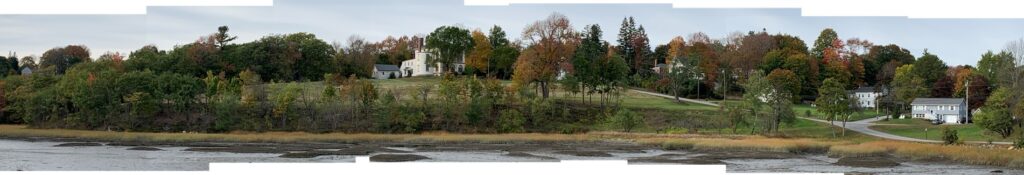
Panorama shooting strategies fall into two categories. One can stay at a single point shooting multiple photos in an arc from that point. These photos when stitched together are form a
panoramic distortion which needs to be corrected. This can be overcome by enlarging the edge
photos with a loss of resolution. Secondly, one can shoot multiple photos as you traverse a trail,
road or the rail line with overlapping views. Using this method, one can eliminate obstructions
by shooting around the obstacle.
It is important to be conscious of the perspective. To stay true to a prototype, the backdrop should focus on the surroundings of the rail line and attendant industries or towns. It is easy to fall into a trap when photographing towns or industries, as one needs to be mindful of where the tracks and rail appurtenances are located as you assemble the photos. The location of the shots is important as elevated photos mask the rails and hide the rail side. In taking photos, the distant view is the most important. The foreground will be masked by your scenery and other scenic items.
Assembling the panoramas is very easy in PowerPoint or a similar program. The photos can be added to a file and cropped or rotated to match up as you move along the scene. Group the photos into a single picture and save them as a file. The example is six pictures making two feet of backdrop. The images may be used multiple times as a mix and match or by reversing the photo. The colors may be better matched in the program by lightening or darkening the exposure.
Measurements are added to the layout backdrop to plan the resulting photo. The measurements show the length along the backdrop and further annotate the elevations at the backdrop to plan the photo. One must pay particular attention to roads, rivers, streams, and elevation changes; and their locations.
Stepping into the photo editing software, one brings the assembled image into the program. The program allows the selection of the canvas size to match the length of the backdrop needed. The program will allow measurements in inches which helps to set up the match to the layout. There is a layer tool to manage the various layers on the backdrop so you can bring in objects to the foreground or background. The program has a variety of tools to manipulate the image. One can select parts of the image, Another area allows the user to rotate, scale, shear, or flip an area of the image. One may smudge or smear a part of an image. One important tool is the clone tool which allows the user to duplicate a part of the image a number of times within the image. To get conformity to the layout topography, one can take the image and shear the edges to match the topography.
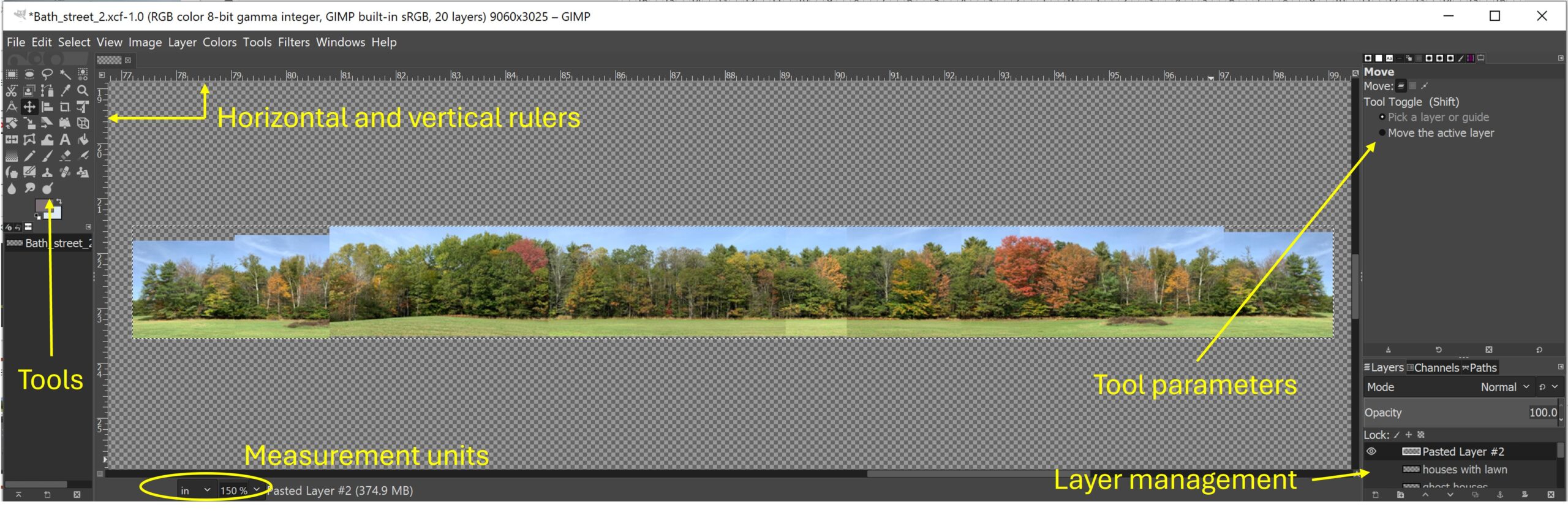
One can remove the sky from the image with the color select tool and remove the foreground grass using the eraser. Moving into the city of Bath, the photo was made up of Google Earth street view images captured for use. The images were not all in the alignment of the buildings as the street view did not capture the buildings
well enough for a straight on view. They were imported as separate layers to allow manipulation of the individual images and match the alignment building to building. The modern items in the frames were erased or covered over with the clone tool to bring in the adjacent building parts such as brick facing or window/door trim. While this detail is time consuming, the results are amazing. He buildings on the individual layers are merged for the
next step. The building layer is then overlaid on the tree layer. This is to mimic the New England scenery. The building backdrop is trees and in this instance, the background houses and a church steeple are added on the edges.
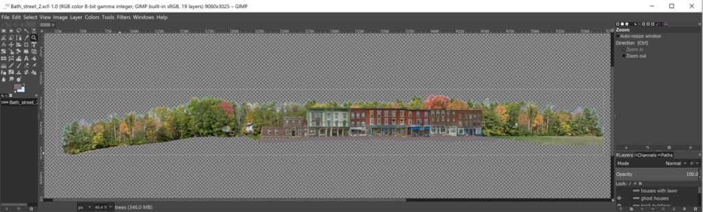
The next step is to test print the resulting backdrop. This is done piece meal on 8 1/2 x 11 paper and then assembled on the layout backdrop. One then has an opportunity to correct the misses in the topography by adjusting the photos to meet the terrain. After the photos are judged to be suitable, the photos are prepared for printing. The individual strips of backdrop photos are stacked on a sheet sized to the length needed. A blue
background is added. All the layers and photos are merged into one .jpeg file for export to the printer.
Rich uses Walmart photo for his prints. The prints are done remotely and are mailed. The photo paper is a thick paper stock with a true flat finish under the photo banner print tab. After receiving the print, the blue is cut off above and below the image with an Exacto blade. Trimming for the trees is very time consuming. The backdrops are mounted to Masonite with wallpaper paste. This allows a bit of working time to adjust the photo. This is a multi-person job. This process is similar to wallpapering, rolling the print flat and matching the seams as you
go along. Add a line of caulk at the base of the print to seal the edge and prevent any water wicking from the later scenery work.
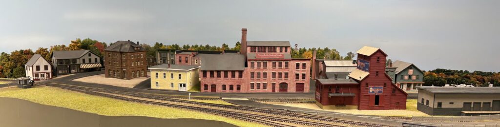
This is the completed scene at Bath. Note the backdrop is visible but largely obscured by the foreground buildings and scenery.
This demonstration went on with a local example. At the mouth of Clear Creek canyon from Tunnel One east, there is hiking trail that follows the creek. This is near the Colorado and Southern alignment from Golden to Blackhawk and Georgetown. Rich captured a number of photographs along the trail to assemble into a backdrop. He demonstrated the process of cropping and arranging the photos into a strip in PowerPoint. After two strips were arranged, they were merged into a single strip to drag into the photo editing software, GIMP. The photo
was enlarged to fit the editing frame. Cars and guardrail were erased from the strip. It is important to remember that the backdrop is not to be a sharply focused item. To that end the resolution on the .jpeg is set to 70 dpi. Further, the panoramic distortion was eased using the distortion tool to even out the horizon line. The sky was erased by selecting a color and erasing that hue. This was too little. So, changing the blue color gave a better result. The trees were returned to one end of the strip by using the clone tool and choosing a representative tree
cluster. The telephone poles in the image were replaced with the nearby grass area again with the clone tool. The concrete weir in the creek was replaced with a log cabin in the trees. A log cabin image was found on the internet and added to the photo in the location.
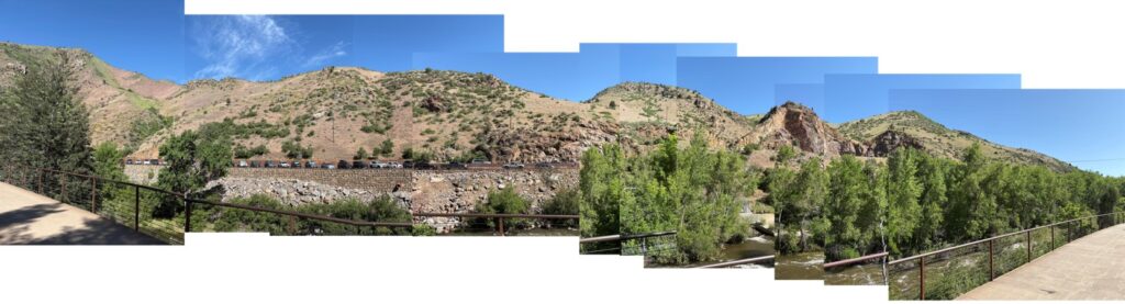
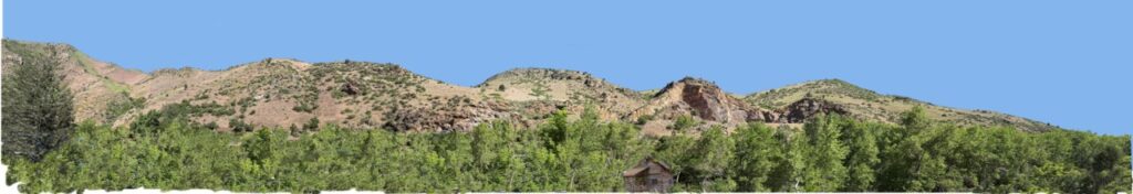
With practice, very little is impossible. The photos may be manipulated to eliminate bridges and shadows. Tree lines can be added by cloning. Today’s photos will need to be edited to move out the modern touches and add historic elements in. The City of Brunswick has lost all of the historic character, so the buildings needed to be replaced with buildings that more closely match the era of the railroad. The benefits are worthwhile.
July Clinic – July 21, 2025
Capturing Night Scenes
Ashley Webb Biography

Ashley received her BA in History and Anthropology from Longwood University, in Farmville, Virginia, and her MA in Museum Studies from Bournemouth University, in Dorset, England. She is currently the Executive Director & Curator of Collections and Exhibitions with the Historical Society of Western Virginia, which operates both the Roanoke History and the O. Winston Link Museums. In addition to her job with the Historical Society, Ashley works with several Roanoke, Virginia, area museums as a contract museum collections specialist and guest curator. Her specialty is fashion history, and she owns Bustle Textiles – a historic dress preservation company with an emphasis on creating traveling fashion exhibitions for small museums.
The photographs of O. Winston Link, 1950s nighttime railroad photographer, who was capturing the declining days of steam power in rural Virginia. These photographs were taken on the Norfolk and Western Railroad from 1955 to 1960. Ashley Webb is the curator of the O. Winston Link Museum in Roanoke, Virginia. O. Winston Link’s influence in nighttime and transportation photography is widely felt even today. This body of work is termed the Norfolk and Western Project. O. Winston Link was born in Brooklyn, New York in 1914. His parents were not New Yorkers but came from the Appalaction country. His father was a teacher and helped his interest in the arts, creativity, and science. He was graduated in 1937 with a degree in Civil Engineering, but at this time it was difficult to find work in the Engineering field. He took a photography position in the Carl Byoir and Associates, a public relations firm. In 1942, Link married Vanda Marteal Oglesby and they had a son in 1945. Also, in 1942, Link was employed by Airborne Instruments Laboratory and was involved in the war effort. After the war, Link decided to become a freelance photographer. They divorced due in part to the stress of developing the photography business.
Link took detailed notes concerning the photographs that he took. This allowed him to retain the information on the photographic set ups and conditions. His interest in railroad photography was fostered during the war years as the Long Island Railroad ran near the Laboratory and he took photos during that period.
In 1955, Link was in Staunton, Virginia, on assignment and he ventured to Waynesboro, Virginia to photograph the train station focusing on the antiquated technology and less than perfect conditions in the area. In conversations with the station agent, Link was invited back the next night with the first image of the Norfolk and Western Project. This photograph showed Train No. 2 arriving at the station in the nighttime image, taken January 21, 1955. Link determined that he should document steam locomotives on the Norfolk and Western as the last major railroad utilizing steam power. He wanted to capture not only the trains but the backdrop of the rural communities and the commitment by the railroad to maintain the operating fleet of steam power. The first night of photography was only seven photos. Planning the project in New York, he enlarged the maps of the routes and consulted time tables. He took several train trips to scout locations along the routes for photography. Roanoke was the Norfolk and Western hub for the branches and served as the major construction and maintenance facility. Over the ensuing five years, Link traveled along the Radford, Pocahontas, and Shenandoah Valley subdivision to take 2,200 photographs largely featuring the steam trains.
To facilitate the project, Link took notes on locations and ideas for photographs. He corresponded with Ben Bane Delaney, the NW Public Relations Manager, outlining his ideas for photographs, but also, making requests for certain events or train locomotive meets. While supportive of the project, Delaney allowed access to engineers, conductors, and re-positioning of the locomotives for photographs, but the project was funded by Link. Link focused not only on the steam locomotives, but the people involved in the operation and maintenance of the machines. The size of the locomotives juxtaposed against the personnel was of fascination to him. The locomotives in many of the photos were in the background with ordinary environmental scenes in the foreground focus. This was apparent in the “Sometimes electricity fails” photo taken in Vesuvius, Virginia. One of Link’s favorite places to photograph the trains was on the Blue Ridge grade requiring double heading of locomotives to make the grade. His fascination with nighttime photography was evident in the photos showing trains at work in towns during the nighttime.
Link took paired photos with black and white film, as well as color film. These images showed the difference in focus as the train were most predominated in the B&W image while the color film added the depth of the surroundings to the image. The color images were mostly taken on the Abingdon Branch of the railroad. The photos brought to light the sometimes confusing naming conventions used at the time. One photo taken in Nella/Husk, Virginia pointed this out. The railroad named the station Nella, while the post office was known as Husk. The station as was common in rural areas functioned as the general store, western union office, post office, and train station. As an expansion of the photo collection, Link also captured sound recordings of the trains and the ambient noise along the line. The color photos add to the beauty of the area like as found in the “Two Pigs in Tuckerdale, North Carolina”. Since this is before the ease of conversion of an image from color to B&W, two cameras were used to capture the paired images with a slightly different camera angle.
The project was under a time and technology crunch. Steam locomotives in the period after
1955 were becoming increasingly rare in favor of the new diesel locomotives. The steam held a little more romance, and certainly showed off more mechanical engineering achievement. A box even a streamlined box moving over the tracks with no visible means of propulsion seemed mundane in comparison. Link used a rather sophisticated lighting scheme for his photographs particularly the night scenes. He added lighting to building faces, background areas, and personnel in the frame. This added attention makes the photos more striking. He used a 4×5 Graflex view camera which meant that he only had one shot to make the image. These photos required that the train be in the right place, the flash units all worked, and that the image was not overexposed. He also traveled with the images undeveloped back to New York for final development. This is another definition of an optimist. Wait to see if your efforts are acceptable. Later, he rented a trailer to use as a mobile film lab to assure better results.
The lighting equipment pressed into service for the night images was impressive. He utilized multi-bulb flash reflectors, multiple single bulb units, and singular flash units carefully placed
for the lighting effects. He created elaborate set up plans showing the train location, foreground and background subjects, flash unit location and type, camera location(s), and the cable to tie this all together. He was charged by one proprietor one dollar a minute for electricity. The flash bulbs used were single use bulbs which meant that to take each image the bulb array needed to be changed for fresh bulbs. Based on the outrageous cost of the electricity, Link devised a method to use two 12 volt lead acid batteries through a convertor to supply the 115 volts needed to power his units. To purchase the supplies for this endeavor, he used the prize money from a photography contest for the photo, “The Meeting of Train No.1 and Train No.2, Hagerstown, Maryland”. The resulting unit was “light” and portable meaning that power could be available without needing outside support. Link also designed a rotating tripod head to tighten all three legs at once, giving more stability on marble or glass surfaces. He also developed some improvements to flash heads. He was very secretive about his work on these inventions and produced the drawings and letters notarized and further mailed to himself via registered mail. Because of this stance, the equipment improvements were not produced for the public.
O. Winston Link was meticulous in planning his work. He produced journals of locations and ideas for photographs in the location. He was very selective and noted some ideas as N.G. or no good in the journals. He would revisit the journal and note the photographs that were taken. The trips were announced to Ben Delaney his schedule and requested that Ben would contact the dispatchers in the area of his schedule. He further contacted people in the area of his intentions. In one instance he utilized the Grottoes Volunteer Fire Department equipment and personnel for one of the night shots. Norfolk and Western Railroad published a magazine, and Link’s photographs were included in at least one issue. Link would use this publication as part of the introduction of the people along the route to his project to generate interest and get participation in the project.
As he received buy-in from people near his chosen locations, he would further map the locations of his lighting, cameras, prop locations, people, and of course the train. An important element to the diagram was the field of view sketched on the mapping. This meant that the lighting elements were outside the view. Link also wrote letters enlisting the assistance of the station agents or others to facilitate his project. He would send cases of flash bulbs ahead of the trip to be held for his arrival. This saved weight in the vehicle and gave a better chance of their safe arrival. His crew car for these efforts was a 1952 Buick convertible. The luggage, cases, reflectors, and cords were packed into the vehicle and loaded and unloaded by hand. The combined weight was 150 pounds, but the volume was the real issue. He had a plan on how the vehicle was loaded to fit everything into the car.
The preparation included daytime photos of the planned locations and his chosen lighting locations. The “Bridge over Hawksbill Creek, Luray, Virginia”, is an example of the photo preparation, the detailed sketch of the location, and model locations for the evening. The first try on this photograph does not show the train on the upper bridge. A letter indicated that another try was to be made the following year. The final image shows all the elements that Link intended. The train is passing over the high bridge, and models are frolicking in the creek. The final image is labeled as the “Hawksbill Creek Swimming Hole, Luray, Virginia – NW1127” . His most famous image is the “Hotshot Eastbound, Iaeger, West Virginia – NW1103-76” . This image includes a drive-in theater with multiple vehicles, an illuminated theater screen, and the train on the embankment just beyond the theater crowd. He began this by writing to the parties involved in the shot. The entire parking area and screen were located inside of the railroad curve. His diagram of the setup shows only the necessary elements and did not include the bridge or the elevated railroad tracks. A good looking couple was requested in his letter to the drive-in owner to use as back of the head models in the front seat of his convertible. The screen in the image was washed out by the flash and the screen image was photographed separately and the screen image imposed on the final print.
One of the most complex photographs that Link made for this project was “Gooseneck Dam on the Maury River, with Train No. 2, Buffalo Forge, Virginia – NW 883”. This photo shows the water cascading over the dam, the distant powerhouse, with an obscured train moving at speed on the far bank. He made a specific diagram of the scene with the locations of the lights, cameras, the field of view, and the schedule to bring the scene together. The schedule included a single up all night notation. A tightrope was installed across the river to facilitate movement of the equipment. A loped rope was used along the tightrope to keep the flash cabling out of the water. Several trips across the tightrope were necessary to get all the equipment into location. The resulting image appears to be a simple photograph but the background work to capture this was intense.
Link kept detailed records on the expenses for each photograph to maintain records in case he could be reimbursed for any one image. He needed to be successful in his commercial photography business to afford the luxury of the NW project. His project covered the line until steam power was fully replaced by diesel locomotives. Along with the change in power came a change in the towns and businesses in the area so his project documented a disappearing life style.
The downside to some of this work was the unfortunate marriage to Conchita Link. She was his agent and had access to his work. She stole some of his work and sold it on eBay through another agent. These works were not fully recovered.
O. Winston Link worked with the City of Roanoke to provide for a gallery space in the lower level of the Norfolk and Western passenger station. This became the Historical Society of Western Virginia. One may link to the webpage at: https://roanokehistory.org/ . The building houses a number of galleries and exhibits.
The Front Range Division wants to thank Ashley Webb for the enlightening clinic on the art of O. Winston Link.
June Clinic – June 16, 2025
Capturing the Character of Trinidad, CO. 1953
Glenn Gibson Biography
Glenn was born in Dallas, Texas, but grew up in the small town of Plattsburg, Missouri, just outside of Kansas City. Glenn’s dad was the International Harvester dealer there, which provided Glenn with summer employment during his teenage years – mostly working the parts counter, but also performing some character-building activities like sweeping out the shop and occasionally helping unload farm equipment from a flat car at the town team track. Glenn attended the University of Kansas in Lawrence, receiving his Bachelor’s and Master’s degrees in Aerospace Engineering. Following college, Glenn went to work at McDonnell Douglas in St. Louis, Missouri. There he met and married Jane, who for some unfathomable reason is still with him after more than 43 years. In 1979, Glenn & Jane moved to Denver, and Glenn went to work for Martin Marietta. Glenn spent many years performing shock, vibration, acoustic, and loads analyses for various rocket programs with Martin Marietta/Lockheed Martin/United
Launch Alliance. He wrapped up his career as an integration manager responsible for ensuring that NASA and Air Force spacecraft were mechanically, electrically, environmentally, and functionally compatible with Atlas and Delta launch vehicles. Glenn participated in rocket launches from both Cape Canaveral Air Force Station and Vandenberg Air Force Base. Probably the most exciting (and nerve-wracking) was NASA’s Mars Science Laboratory mission, which placed the Curiosity Rover on Mars. Following retirement, Glenn & Jane moved from Conifer down to Lakewood, and Glenn became a member of the Front Range Division of the NMRA, and the Lockheed Martin model railroad club. In addition to model railroading, Glenn enjoys taking classes on a wide range of topics through Osher Lifelong Learning Institute (OLLI) at DU, and he and Jane will continue traveling.
Glenn Gibson will discuss how he has attempted to capture the character of Trinidad in a small corner of his HO scale AT&SF Trinidad & Raton Pass layout, which is set in 1953. The area of concentration is Commercial Street near the Purgatory River and the Santa Fe tracks and station. The chosen area has an eclectic mixture of commercial buildings, hotels, bars, cafes, warehouses, and repair shops. He has mainly utilized commercially available materials and structures, modifying and kitbashing them as needed to get the look desired and to fit into the space available. A mirror was used to expand the space, and he will “reflect” on the pros and cons of using that method. His review will include modeling the river and the Commercial Street bridge.
Glenn Gibson conveyed his efforts to build out a corner of his layout to represent the 1953 era Trinidad, Colorado. He began the program by showing a photo of Commercial Street in Trinidad with the Trinidad logoed bricks paving the way. Trinidad Brick and Tile was in the business of making these paving bricks which were used in a number of cities, including San Francisco and Minneapolis.
Trinidad was founded when Felipe Baca had 11 families move to the Trinidad area in 1862 with the Town of Trinidad coming into existence in 1866. The AT&SF Railway arrived in Trinidad in 1878. Some claim that they beat out the D&RGW railroad for the route over Raton Pass. The reality of this rivalry is less clear, but the Santa Fe built their railroad over Raton Pass. In a nod to the old west, Bat Masterson was the police chief in 1882 and kept Doc Holiday safe from extradition to New Mexico. The late 1880’s saw the coal and coke mining boom arrive in the area and pushed the town into the middle of the railroad crossroads. The town had Santa Fe Railroad with a large presence and D&RGW with the Colorado & Southern Railway were also servicing the area. Isaac Hamilton Rapp & William Mason Rapp were Architects with an extensive practice in the area designing over 175 structures in the region. They used Trinidad Brick and Tile, established in 1901, in many of the buildings adding cohesion to the design efforts and the style of the area buildings. The years 1913 and 1914 were the Colorado Coalfield War between the United Mine Workers Union and Colorado Fuel and Iron Company, which culminated in the Ludlow Massacre of 1914. The population of Trinidad peaked in 1950 at 14,000. More recently, Dr. Bieber established the town as the sex change capital in the 1970’s and 1980’s. Dana Crawford brought her renovation expertise to Trinidad in the 2010’s and 2020’s. This is later than our focus time period.
The Trinidad and Raton Pass layout is housed in a 13-foot by 19-foot free-standing shed. The layout is taking shape as a three-level effort with the primary focus as Trinidad and the Raton Pass railroad area. The layout has some Colorado and Southern modeled areas. The era was established as 1953 as this was the last year of steam locomotive helpers on the Santa Fe to make the grade to Raton Pass. This leads to the definition of “capturing character” of Trinidad. Rather than spend a good deal of time replicating off railroad structures by scratch building, commercially available kits were used to convey a sense of the area. Glenn focused on several elements which to his mind replicates the feel of the area. These include brick streets, 1900’s era one, two, and three story buildings, signage painted on the sides of the structures, and an eclectic mix of hotels, cafes, commercial buildings, warehouses and repair shops. The foreground of the street assemblage is to include the Purgatory River and road and railroad bridges.
Glenn included some inspirational photos of Trinidad.
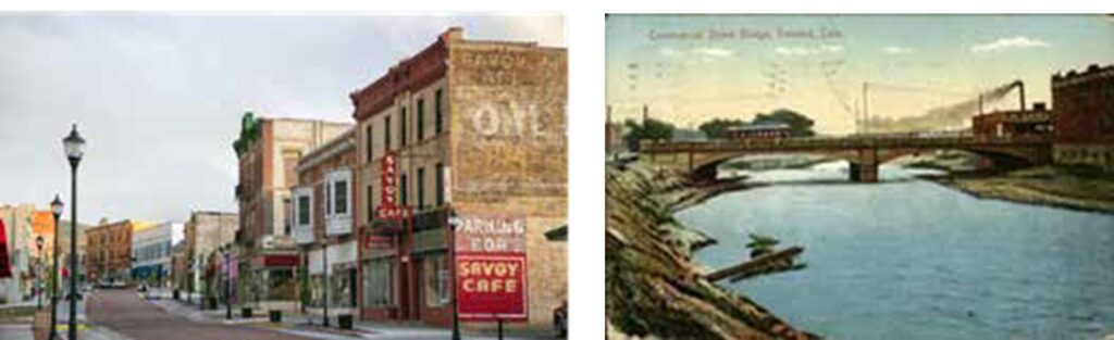
The blue balconies of the Trinidad Hotel were particularly interesting. Hausman’s Riverside Drugstore was another interesting structure located right on the river. Glenn was able to make use of the Sanborn Insurance map of the Trinidad area which helped guide the type of businesses located on the street and the construction material used for the structure. The majority were brick construction with a few stone buildings. Wood frame structures were rare on the Commercial Street.
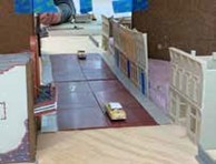
This representation was given a 2 foot by 2 foot triangular corner of the layout. In order to fit this in, mockups were in order. Copies of the Walthers Cornerstone Brick Street sections were used to test fit and verify the exact needs for the street. The paper copies were used as the final template for the assembled street sections. To allow for a larger street scene Glenn used a mirror as an extension device. He started with mirror tiles from Home Depot to test fit the location and orientation of the mirror. When he was satisfied with the location, he measured for the front faced mirror panel which was quite expensive. There were lessons learned from the experiment on mirrors. Mirrors reflect everything. Keep the mirror positioned so visitors will not see themselves reflected in the mirror. Keep vehicles at a distance from the mirror to avoid the impression of a head-on collision. Keep edge structures perpendicular to the mirror. Pay attention to reflected signage. Mirrors have hard edges that need to be concealed. In this instance, the left edge of the mirror is concealed by a three story building and sign. The top of the mirror is hidden by the upper level deck.
The buildings along Commercial Street were developed by mocking up the streetscape using a variety of construction types. Some of the buildings were pre-built, Woodland Scenics buildings. Others were partially built from previous projects. There were a number of DPM kits used to make up the scene. Determining the building fit was determined by making copies of the DPM building fronts and sides and pasting the copies to foam core shells. In other instances, a foam box of an approximate size was made up to fit the location. This approach resulted in a collection of models that were kit-bashed, a couple of scratch built structures and one prebuilt theatre. Since the predominate material was the Trinidad brick, the paint used was Rustoleum 2X red primer & nutmeg brown. The mortar lines were made with Roberts brick mortar. This gave rise to some discussion on the use of this material. Glenn adds a thinning agent to the mortar and applies it to the structure. Don’t leave the material on too long or it is difficult to remove and covers the wall surface. Rustoleum 2X Fossil and Khaki were used for the aged concrete and Tamiya light gray was used for new concrete color. The structures were lit with Woodland Scenics Just Plug system. The window signs and stained glass panels were created in PowerPoint and printed on transparency film. The other signs for the street were created in PowerPoint, printed on plain paper, and sanded thin to apply to the walls. Miller engineering signs were used for the animated signs. The interiors for the buildings were City Classics photo interiors.
Stepping down the street, beginning at the location of the mirror, the first building is the Savoy Café. This is a DPM Other Corner Café kit. The sign is a photo of the actual sign but glued to the mirror for no reflection. The window signs are icons of the food items rather than words as the mirror reflection of the “other” half of the building would distort the printing. The DPM Roberts Dry Goods kit was used for the Myers Hardware building. The sign that projects from the building calls out Myers Hardware on the front side with a reversed image sign on the rear stating “Trinidad Furniture”. A Monster Model Works awning was attached to the front of the structure. Next up is Glancy’s Irish Pub & Pool Hall which is a DPM Kelly’s Saloon. This was pretty much a stock representation, but the buildings are getting to be deeper as we move from the corner.
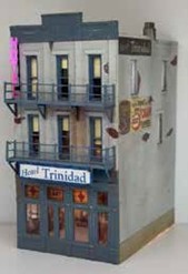
Hotel Trinidad is a signature structure on the street with blue balconies. This building started as the DPM Walker Building. The interior lobby is a photo of a hotel lobby scaled to fit the building. An animated “Hotel” sign is affixed to the corner of the building. The building side to the mirror has a reverse sign. The front facing side of the building was grey painted with application to resemble peeling paint. Brennecke’s Bakery building is a small building scratch built from Monster Model Works brick siding and the interior was a City Classics photo interior. The movie theatre is the Woodland Scenics Built & Ready theatre building with no changes.
Moving across the street are Hausman’s Riverside Drug Store and Donna’s Dance Studio. This was made up of the DPM Carr’s Parts building front with the sides and back from DPM Robert’s Dry Goods. This orientation gave the loading dock at the rear of the store.
This building and the movie theatre were switched sides of the street to allow more visibility of the loading dock from the aisle. The upper level was populated with Woodland Scenics dancer figures. Another animated sign is attached to the front of the drugstore. Moving toward the mirror, Schwarz’s Machine Shop is made from DPM Schultz’s Garage. The roof was lowered a bit to shorten the profile. The J.F. Sherman Mercantile Co. is the large three-story building near the mirror. This was an extensive kit bash shorting the length of the building but retaining the height. The building was used to hide the edge of the mirror with the rooftop water tower and billboard sign.
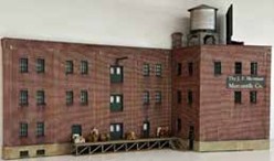
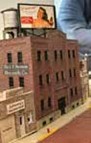
The Welding Shop was built with Monster Model Works stone siding. This is a small structure with action detailing out front.
Lighting for the structure interior and exterior, streetlights, and vehicles is provided by the Woodland Scenics Just Plug Lighting System. An expansion hub powers three light hubs with four ports each. Some items need to be wired to a plug for the connection. The tiny wires are coated and need to be stripped of the coating for connection. This can be scraped off or burned off.
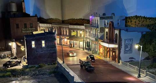
Some light leakage was noted in the scene. This was corrected by using black electrical tape folded in half, anchored to the walls of the building and loose against the base.
Glenn has a number of figures and vignettes around the town. This adds interest to the areas about town. Checker players, young people at the rear of the dance studio, the discussion group at Glancy’s Pub, and the gathered supervisors at the welding shop all add life to the layout street and interest to the detailing of the area. The Purgatory River was made using two boxes of Woodland Scenics Deep Pour Water tinted with Sage Green Tint. The water is clear matching the Colorado locale.
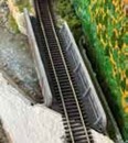
The ripples were added with water effects and dry brushed with white. To add more realism to the river scene, junk was added to the water. This includes tree branches, oil drum, tires, pipe, and an auto chassis. Storm drains were added at the banks. Bridges were added over the river. The Colorado & Southern bridge is a through girder bridge and the D&RGW bridge is a silver representation. The bridges were a Walthers Cornerstone Bridge cut at an angle for the crossing.
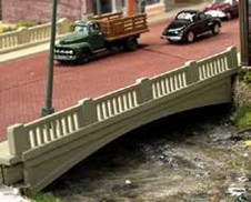
The Commercial Street bridge is made of a plywood sheet with brick paving added. The railings are Rix Products Vintage Highway Overpass Railing with the concrete girder below cut from styrene sheet in a 15 inch radius for the gentle arch.
Using the services of Paul Brennecke to take photographs of the complete scene, we get the street view image of the area, using stacked photo technique.
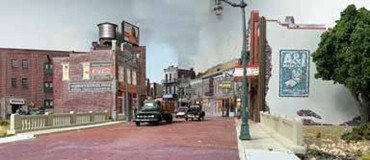
Moving into the railyard, the scene looks like this:
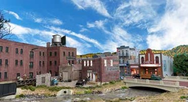
May Clinic – May 19, 2025
The Missouri Pacific Railroad in Colorado
Bob Hochstetter Biography
General dentist for seven years. Then a prosthodontist (specialist) for 30 years. Retired from the Department of Veterans Affairs where he treated mostly injured and retired veterans. After retirement, he worked at Caboose Hobbies doing N scale and Z scale repairs and decoder installations for seven years until the store’s closure. Followed by volunteering for 6 years doing income tax returns for moderate to low-income individuals 55 years and older for AARP Tax-Aide.
Bob will present his interpretation of “The Missouri Pacific Railroad in Colorado”. Making use of employee timetables, we will discuss the MP from its entry into Colorado until the Union Pacific takeover and beyond. We can answer the question, “Why are Railroads magnetically drawn to Pueblo, Colorado?” Or “How far can Rocky Ford Melons travel?”
Bob Hochstetter helped the Division understand the Missouri Pacific Railroad’s operations in Colorado with the use of Employee Timetables and photographs. The Pacific Railroad was chartered in 1852 by the State of Missouri to extend from Saint Louis to Jefferson City, and then further to the state line and the Pacific Ocean. It is still amazing to the editor the number of railroads attempting to reach the Pacific from Pueblo, Colorado.
The first train run was from Saint Louis to Cheltenham in December of 1852. By 1872, the Missouri Pacific Railroad was formed from the remnants of the Pacific Railroad under the control of Jay Gould. By 1887, the Missouri Pacific (MP) had reached the Colorado-Kansas state line. A new entity, the Pueblo and State Line Railroad began construction of the line west to Pueblo in 1887 and the line was completed in that year. This was 152 miles of standard gauge track with a maximum grade of 0.9%. The line was sold to the MP in 1910. The Pueblo Union Depot was constructed in 1889-1890 to serve the ATSF, DRGW, Colorado and Southern, Missouri Pacific, and the Chicago Rock Island & Pacific Railroad. The routing of the line traversed Crowley, Kiowa, and Pueblo counties in the southeast portion of Colorado and largely followed the Arkansas River.
This portion of the MP served largely as a bridge route between Kansas City and the DRGW railroad. The MP system at its height had over 11,000 miles of track.
The study of the line can be accomplished by examining the employee timetables. The 1927 version shows the following information in each direction:
- Two passenger trains – #12 – Scenic Limited from Pueblo to St. Louis with two stops in route, and #16 – an unnamed passenger train with multiple stops.
- Two Red Ball through freight trains
- Two local freight trains
- Functionally – 8 water stops in the route with 3 scheduled and the others as needed, mail cranes, depots, wyes, and turntable locations
- The route was a timetable, train order-controlled branch with three (3) continuous train order offices.
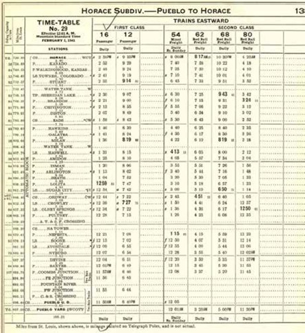
The 1941 timetable shows similar information in each direction with some changes:
- Two passenger trains – #12 – Scenic Limited from Pueblo to St. Louis with two stops in route, and #16 – an unnamed passenger train with multiple stops, but the westbound train named the Royal Gorge.
- Three Red Ball through freight trains
- One local freight train
- Functionally – 4 water stops in the route with 2 scheduled and the others as needed, mail cranes, coal station, telephone communication or telephone/telegraph,
- The route was at this time an automatic block signaled route with fewer continous train order offices and limited train order offices (manned only during business hours), but still operating with timetable/train orders.
Moving forward to the 1958 version of the time table, we find some differences. The entire timetable is now on one sheet. One notable change is the addition of two track areas nearing Pueblo. From Coombs Junction to the Fountain River, the line had two tracks over the Fountain River was a single track bridge, and from the Fountain River to the Pueblo Yard the line was two tracks. Crossings are also noted on the timetable, one with the ATSF, one with the Colorado and Southern, and finally with the CB&Q.
The timetable shows 152 miles from Pueblo to Towner, which is at the Kansas border. No distance modification was made as the line was rerouted particularly around curves. This means that the distance is less than indicated. There is a distinction between stations and depots. The station is a railroad designated location, while a depot would be a physical structure at the named location.
Facilities were provided along the route at designated locations. Wye tracks were found at Eads, Ordway, and Pueblo. Yards were located at Sugar City and Pueblo. The turntable at this point was located at Pueblo with diesel fuel available. Track scales were available at Sugar City and Pueblo. The route still used timetable/train order control until the Pueblo yard where it switched to continuous train order office control. An oddity of the timetable is that Y is a yard while W is the designation for a wye. Access to the single-track bridge was controlled by a manned control point. Communications for this period was by radio with the line having seven base stations coupled with the continued use of telephone, and limited telegraph availability. Interspersed on the line are limited train order offices.

The trains found on the route include the Colorado Eagle. This is a signature train for the railroad which was actually operated by Denver and Rio Grande Western personnel from Pueblo to Denver. The train was #12 on the MP and changed to #3 when it was on the DRGW. It was an 18-hour trip from St. Louis to Denver. This train was painted in the Eagle Grey scheme with no exceptions. No foreign cars could be coupled into the train and any freight needed to be offloaded and reloaded into the MP cars.
Part of the documents located for the MP included arbitrary holds for passenger trains which indicated that the Eagle would be held at Pueblo for the Denver and Rio Grande train. This is unusual as the equipment is the same for both the MP and DRGW trains. Further in keeping with the joint line use from Pueblo to Denver, the northbound Eagle stopped at the ATSF depot in Colorado Springs while the southbound train stopped at the DRGW depot in Colorado Springs.
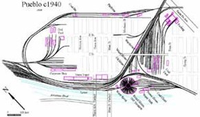
This is a map of the Pueblo depot and yards. The MP enters from the upper right and continues around the loop of track to stop at the depot in the lower center of the map. After the crew changes at the depot area the train exits the yard complex to the north at the upper right. The route crosses itself to make its way to Denver.
The number of Red Ball freights has increased to two each way. One tonnage freight is in the timetable. This is a train that carried low priority freight, and the foreign cars needed to be returned to the home road. This is the period of per diem payments, so the foreign cars need to be returned as quickly as possible. Two local freight trains were in the timetable. The local freights’ only switched cars at 3 locations along the route. These locations are found by examining the length of time between stations. Normally the train has a few minutes between points. The switching locations allow an hour to make the next station, which may be five (5) or so miles distant.
Meets between trains can be found in the timetable by examining the small numbers annotated next to the station/train indicator. The trains can be in the same location but a siding needs to be located at the meet location. The eastbound trains have the right-of-way on the MP and so an eastbound train would occupy the main and the westbound train would need to be on the track siding as indicated on the timetable. The passenger trains have right-of-way over freight trains, even a red ball freight. The timetable contains information on siding capacity. The number of cars is indicated in 40 foot car lengths and would need to be adjusted for the cars carried by the train. This figured into the length of train assembled in the yards to be certain that the meets could be accommodated by the siding length.
The unfortunate locale of this subdivision is that the MP did not carry a lot of tonnage. The tonnage map shows from 1.0 to 1.99 million net tons annually. This compares to other MP trunk lines carrying up to 4 million net tons.
Prior to 1951, the railroads noted that they were losing less than carload freight traffic to other carriers, principally trucks. The MP started their version of merchandise service as the Eagle Merchandise Service. These were specially painted and detailed cars with pallet size metal containers. These containers were on wheels for ease of handling, but were made to be fork lift truck-unloaded at major terminals. This service lasted from 1951 to 1960. The stations served included Avondale, Crowley, Eads, Haswell, Sheridan Lake, Sugar City, and Towner.
Pueblo was the major terminal for the service. The railcars were quite old ranging from 1925 to 1929. The oldest started as wood side cars with metal sheathing added later. All the cars received special paint and graphics to identify the service.
Regular on-line shippers for the division were rare. In Avondale, there were two vegetable warehouses, a cantaloupe and onion shed, the Army ordinance, and a sugar beet dump. In Nyburg, the division serviced an onion warehouse, and a sugar beet dump. Nyburg is a location west of Avondale about 5 rail miles. The rail line regularly serviced the sugar factory in Sugar City.
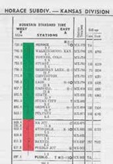
This is the 1982 timetable for the subdivision. It is important to note that no passenger trains are listed. There are no regularly scheduled freight trains. There is a manual interlocking at Pueblo Junction. There is one wye noted at Sugar City, but no sidings or yard tracks remain at that location. The sugar plant closed in 1967. The division has 5 radio base stations. ABS signaling is in use from Towner to the North Avondale Junction. One 50 mph equivalent turnout is noted at that junction. MP merged with Union Pacific in 1982.
Moving back in time to the 1888 MP Annual Report, for this Division fifteen locations were listed. This amounts to a location every ten miles to accommodate delivery to the railroad of grain by horse and wagon. The towns that were noted on the 1888 map become fluid over the years until 2014. Many of the locations disappeared and a few new names were added. The lasting towns were Sheridan Lake, Chivington, Eads, Haswell, Arlington, Olney Springs, Boone, North Avondale, Baxter; and, of course Pueblo. Added into the roster were Sugar City, Ordway, Crowley, and Towner. One can follow the track from Pueblo into Kansas. The road begins as US 50 from Pueblo east to North Avondale where the highway junctions with Colorado 96 to parallel the tracks east. Beginning at the Kansas state line, the first MP location is Towner, Colorado. This is a census designated place with a population of eighteen (18) at the 2020 census. This town still sports a Cargill elevator. The next location is Sheridan Lake with a population of 55 in 2020. The elevator here is rundown. Chivington is the next location on the route with no listed population, but a sign welcoming you. Eads is the county seat of Kiowa county with a population of 672. The elevator local farmers use here seasonally. Haswell is next up on the travel log with a population of seventy-one (71). The elevator is at a Scoular location. Sugar City is where MP had a yard and serviced the National Sugar Manufacturing plant. It has a population of 259. The elevator still operates as the Sugar City Grain Company. Ordway is the county seat of Crowley County. It has a population of 1,066 as of the 2020 census. Crowley is the next location on the MP route. It has a population of 166 and is the location of the Crowley Heritage Center. Proceeding west, you encounter Olney Springs. This town has a population of 315. Boone Colorado is in Pueblo County and has a population of 305. They have re-purposed the Santa Fe depot into their town hall. Avondale is a census-designated place in Pueblo County with a 2020 population of 594. It is now part of the Pueblo Metropolitan Statistical Area. And finally, we reach the Pacific or rather Pueblo, Colorado. This city has a population of 111,077. It has the Pueblo Union Depot which is a depot in name only with no remaining passenger service. It is now noted as a wedding venue.
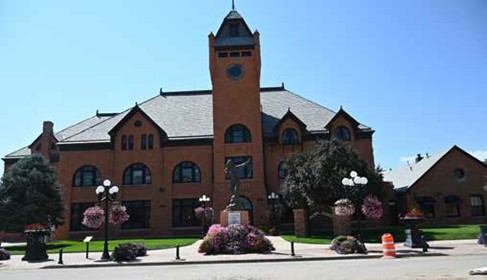
The Missouri Pacific trackage in Colorado suffered from a checkered modern history. After the 1996 abandonment approval, the State of Colorado stepped up in 1998 to purchase the line.
The line was leased to the Victoria and Southern Railroad in 2004, and the V&S petitioned Colorado Department of Transportation to dismantle the rails from Towner to North Avondale Junction. This petition was denied. Stefan Soloveiv purchased that portion of the line in 2016. Improvements were made to the line, and it is now operated as the Colorado Pacific Railroad.
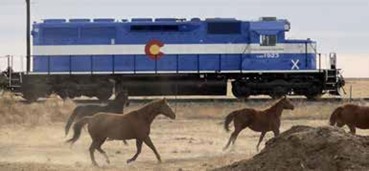
The locomotives are sharply painted. The website reports interchange with BNSF and UP at the western end of the line and interchange in Kansas with another short railroad line. The line lives on with investment in improvements at North Avondale, Sheridan Lake, and Towner.
References:
Personal communications from the following members of the Missouri Pacific Historical Society:
- Jerry Michels
- Charlie Duckworth
- Ron Merrick And from:
- Norm Metcalf
- Perry Scheuerman
- Carl Fankhauser Wikipedia
American-Rails.com The Colorado Eagle by Adam Burns Route of the Eagles by Greg Stout
Missouri Pacific Eagle Merchandise Service Brochure – 1957 Missouri Pacific Circular 140-P
And:
The Empire that Missouri Pacific Serves – 1956 by Missouri Pacific Railroad
Bob noted during his travels from Denver to Durango that another Soloveiv railroad called the Colorado Pacific Rio Grande Railroad is operating on the D&RGW tracks in the San Luis Valley. This line uses the same snappy paint scheme and hauls potatoes, barley, and minerals. The interchange is at the east end of the line with the BNSF and UP at Walsenburg.
April Clinic – April 21, 2025
Clinic – Atomic-Age Narrow-Gauge: Uranium and the Rio Grande Southern Railroad
Steve Hart Biography
Steve Hart is a retired geological engineer who worked at a number of radioactive remediation sites—mines, mills, and processing plants. One UMTRA project was the 1881 lead-silver Durango Smelter, which was converted into a vanadium-uranium mill in the 1930s. Another was the Denver Radium Sites Superfund Project, which cleaned up 40 WWI-vintage “Radium Boom” sites.
Steve gave his presentation of “Atomic-Age Narrow Gauge, Radium, Vanadium, and Uranium, and the Rio Grande Southern Railroad”. The Rio Grande Southern (RGS) was constructed to reach the rich silver mines in Southwest Colorado. The railroad tied to the Rio Grande Western at the north and south terminus. The RGS was completed in time for the Silver Panic of 1893, which meant that it lost most of the lucative silver business. As luck would have it, Madame Curie discovered Radium from an Austrian source. Yellow ore from Colorado was sent to France to be indentified and it was discovered to be another source for Uranium. The mineral, called Carnotite, was found in an arc along the San Miguel River and named the Uravan Belt. The RGS could load this material in Placerville relatively close to the mines located in Uravan, Vanadium, and Nucla.
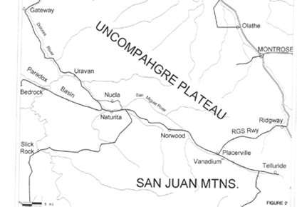
The boom was started by Rare Metals Mining and Milling Company in 1900. The first U.S. radium extraction plant was constructed in Naturita in 1901. The name of the company was changed to Western Refining Company and then changed to Dolores Refining Company by 1904. In 1908, the company was named American Rare Metals Company. The enterprise was profitable by shipping the refined ore to Europe. The company was headquartered in Denver.
In 1910, the Bureau of Mines established an office in Denver to foster the development of Radium, Vanadium, and Uranium exploration. Also, in 1910, the Primos Chemical Company built a mill at Newmire, later renamed Vanadium. This was directly accessed by RGS.

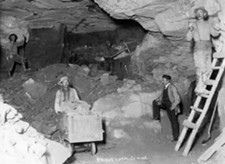
The Primos Mine is shown in the photo above. The mine was lit with candles and had minimal shoring or other safety measures. This is radioactive material mined by hand. There were three separate mines feeding the mill.
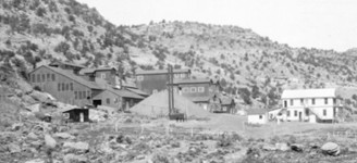
Standard Chemical Company of Pennsylvania constructed the Joe Jr. Mill at Uravan on the river. The mill was accompanied by a boarding house in 1914. Transportation west from Placerville was by horse drawn stages or on horseback. This meant that any mining or mill equipment needed to be freighted west by wagon or on mule back. The processed ore was loaded in 100-pound burlap bags and freighted by mule to Placerville to be loaded into box cars for shipment to Denver and other points.
During World War One, Standard replaced the mule or wagon transportation with Mack trucks with trailers to haul the ore to Placerville. Later, this was replaced by tanks of slurry loaded into narrow gauge tank cars and transferred to standard gauge tack cars at Montrose. In the era of 1913 to 1916, the National Radium Institute was established in Denver. This was brought about by two doctors wanting radium for cancer treatment in the U.S. So much of the partially processed material was being shipped to Europe and the U.S. needs were not being met.
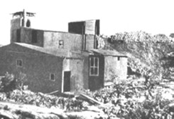
Research by the institute found that pertified logs or dinosaur bones within the formation held a higher concentration of the rare earth minerals. This was the replacement of the organic compounds by the dissolved salts in the item. The Institute had a dedicated mill, the Long Park Mill. The mill was designed to produce 7.5 grams of metallic radium. The mill produced 11 grams of material in three years at a cost of $80,000 per gram.
The value of the Carnotite produced in Colorado had two peaks. The first peak in 1914 saw a value of the ore at $2.7 million with the second peak in 1918 at $2.3 million. The value of Radium in 1914 was $55 million per pound.
With this value there were a number of enterprises founded. One of them was the Radium Company of Colorado. The offices were located in Denver at 18th and Blake with a processing plant located on Tejon Street adjacent to the Colorado and Southern narrow gauge line. A subsidiary of RCC was the Cold Light Manufacturing Company. This was located at East Colfax and Race Street. They produced glow-in-dark aircraft dials, watch faces, and rifle sights. The faces were hand painted by young women. The human cost was high as the workers fell ill with cancers from handling and abusing the radium sulfide.
In 1916, the Bureau of Mines relocated their offices and labs to Golden on the School of Mines campus. The facility stayed in that location until 1920 when it moved to Reno, NV. In a typical Colorado fashion, the Radium boom went bust in 1922. A much richer ore was found in southern Congo in 1914 but was kept secret until the end of World War One. The processing plant in the Congo was designed by RCC. By 1923, the miners left the Uravan District and the dream of Radium riches was over in Colorado.

The late 1930’s ushered in a new era in the Uravan District, as the U.S. ramped up production of armor planting for ships and tanks. This required a source for Vanadium. The Vanadium Corporation of America constructed a new mill at Naturita.
The Durango Silver-Lead smelter was converted to Vanadium production in 1939 after being closed for 10 years. This production was sustained until 1943 when the smelter was converted again to process Uranium. The workers were not informed of the change in production.
The tonnage moved by the Rio Grande Southern peaked in 1944 as shown on the graph. The tonnage moved online peaked in 1943 as that was the last year of gold and silver production. The precious metals production was terminated by executive order in that year.
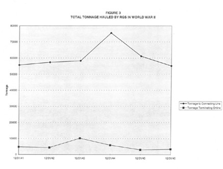
The use of RGS was not without risk, as the 455 locomotive was wrecked in 1943. The locomotive was not rebuilt until after the war when a new steel cab was added.
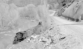
The Bureau of Public Roads constructed 334 miles of roads in southwestern Colorado during World War Two. This lessened the demand for rail transport and boosted the trucking industry. The end result of this was that by 1945 trucks replaced trains for hauling Uranium. The roads were gravel surface affairs with minimal safety features.
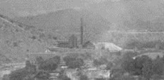
The Durango Uranium Plant operated by USV reopened in 1948 and operated unitl 1960. The light colored tailings pile outside the plant are uranium mill tailings which were later moved to a nearby valley for final disposal.
The RGS continued to operate by trying to convert the uranium business into tourism and scenery. The railroad ceased operations in 1952 after the loss of the mail contract.
The legacy of the Uravan Mineral belt is a series of hazardous material cleanups spanning from 1983 to 2000. They include:
- Uranium mills at Durango, Naturita, Dove Creek, & Slick Rock cleaned up under Uranium Mill Tailings Reclamation Action, 1980 – 1989
- Primos Vanadium – 1990’s Superfund site
- Mines reclaimed by Colorado Mined Land Reclamation Division in 1990s.
The Uravan site was cleaned up as a Superfund site completed in 2000. The only remaining buildings on the site were the State of Colorado Landmarked boarding house and stables. The structures were destroyed in 2007 by fire. This points out that landmarking a property is not preserving the property for the future.
The cleanup activities moved into the Denver area. The National Radium Institute property was later used by Robinson Brick and Tile with the 1917 buildings still on the property with some use. The site was cleaned up as a Superfund Site which included 40 sites around the Denver area.
The clean up extended into Golden on the School of Mines former Bureau of Mines offices and labs. The 1894 buiilding was decontaminated in 1988.
There are few reminders of the Radium boom in Colorado. A mining structure here or there and the tailings piles sattered about the Paradox Valley.
The RGS has a few more artifacts remaining. Locomotive 20 is in use at the Colorado Railroad Museum. Galloping Geese are found in a number of locations, including the CRRM, Knotts Berry Farm, Telluride, and Dolores. A repilica Goose is found at Ridgway. The water tower is located at Trout Lake and the depot is in use at Placerville.
Further reading can be found in these references:
- Uranium Country. Kathleen Bruyn, 1955.
- “The Denver Radium Boom and the Colorado School of Mines” in Mines Magazine, March 1986. Stephen Hart.
- Yellowcake Towns: Uranium Mining Communities in the American West. Michael Amundsen, 2002.
- Radium Girls: The Dark Story of America’s Shining Women. Kate Moore, 2017.
Steve Hart also indicated that the Mining History Association Conference will be held June 11- 15, 2025, in Gunnison. Information can be found at: https://www.mininghistoryassociation.org/Gunnison2025.htm#:
March Clinic – March 17, 2025
Clinic – Deep in the Freight Yard
Scott Ogle Biography

Scott was born in Seattle, Washington, where his love of trains began riding the Great Northern’s Empire Builder & the Northern Pacific’s North Coast Limited to visit grandparents living in Spokane.
The son of a corporate nomad, Scott lived in Seattle, Phoenix AZ, Bellevue WA, & Marin County CA before graduating from high school in Honolulu.
Several HO railroads were started but left behind in those years. Faced with the choice of Vietnam or college, Scott did his research carefully. He noted that his favorite activity, skiing was not available in either the ‘Nam or Hawaii, but the University of Colorado offered white powder, red tile roofs, and a reputation as a party school. Guessing they probably had classes too, Scott moved to Boulder in 1967 to attend CU, majoring in Broadcasting.
After (miraculously) being graduated from college, Scott worked his way around various Colorado TV stations, shooting commercials, documentaries, and local news for KKTV, KMGH, KUSA, and KCNC, eventually becoming the Boulder correspondent for NewsCenter4. After a few years, Scott quit local TV to become a freelancer, traveling the world working for pretty much every broadcast & cable network that identifies itself with 3 or 4 capital letters. Although Scott covered many major news events, he specialized in sports; producing, directing, and shooting everything from World Cup Skiing, through the Olympic Games, Ironman World Championships, Le Tour de France, and 10 years of being the embedded NFL Network crew covering the Denver Broncos including their 2015 & 2016 Super Bowl seasons.
Angela, Scott’s wife of 33 years passed away in 2008. After five years, Scott decided their home in Boulder had too many ghosts to remain living there and moved to a 55+ community in Broomfield in 2013. The new home came with a huge walkout basement that Scott decided was too nice to just store stuff and really needed a model railroad to reach its full potential. So, after Scott retired in 2017, he started building “The Snoqualmie Branch”, inspired by a real-life Northern Pacific branch line that went near Scott’s childhood home in Washington State.
Scott Ogle presented his clinic on “Deep in the Freight Yard”. This was a discussion of the evolution of the major freight yard for his Snoqualmie Branch. This model railroad is a depiction of the Great Northern/Northern Pacific Railroads in Washington State near Seattle. The layout started as a switching layout on a 32 inch by 144 inch long table top which quickly grew to 15 feet in length. He added to this plan with the Mountain Division. This module had a ruling grade of 2.2% with 150 feet of track. The minimum radius was 36 inches. The height was 12 inches, and it took a 3 lap spiral to get to the Cascade Tunnel. This also marked his journey into track planning software to make more efficient use of the available space. As part of the journey, the Snoqualmie Branch no longer described the railroad. The railroad needed to expand into Seattle with the harbor and large freight yard.
Scott read and studied all he could on freight yards, design of freight yards, and construction of model railroad freight yards. The simple definition of a freight yard is a series, 3 or more, of parallel tracks for storing, sorting, and making up trains. Freight yards come in a variety of types from simple interchange and junction yards, industry off spot and storage, and division point and terminal yards. The size and complexity of the yard operations increases as the steps up in yard importance. Scott gave examples of the types of yards and how they operated for the railroads. One of the larger yards on the BNSF system is the Jarlsberg Yard, which is a large yard with a hump (gravity) sorting facility and many sorting tracks. Seattle has a very complicated yard with train traffic from the north, south, and east. Western freight is carried on ships or barges to and from all points. The train freight can be controlled, but ocean freight is more random and has a large volume. This requires a number of storage tracks for empty cars. Northern Pacific originally had a yard near this location.
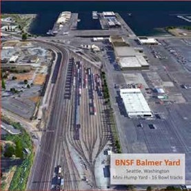
Design of yards takes some coordination as the road crews should not enter the yard, yard crews should not occupy the main, and yard trains should not cross the main line. This means that service facilities should all be on one side of the main for easy access. One should not be clever in the design of the yard. The yard should be very straight forward. Towns or industries can be designed to be more challenging, where the operator needs to work a little harder to accomplish the switching tasks.
Since the yards work at a slower pace than the fast clock mainline, they need to operate very efficiently. Scott put together his givens, and druthers for the design of his railroad yard:
- Design for high volume of traffic.
- Double ended yard, easy in and out.
- 2 1/3″ track spacing for HO scale equipment to handle cars and read car numbers.
- Utilize diamond design with #6 turnouts with yard tracks all the same length.
- Simple ladders, no compound branching.
- Drill tracks long enough to handle full train consists.
- No mainline crossing to reach the yard.
- Restricted access to drill tracks.
- Accommodate 2 to 3 person yard crew.
- Easy access runaround track.
This is the layout as currently designed. The yard in question is in green in the left central portion of the diagram. This has incorporated the elements that were desired.
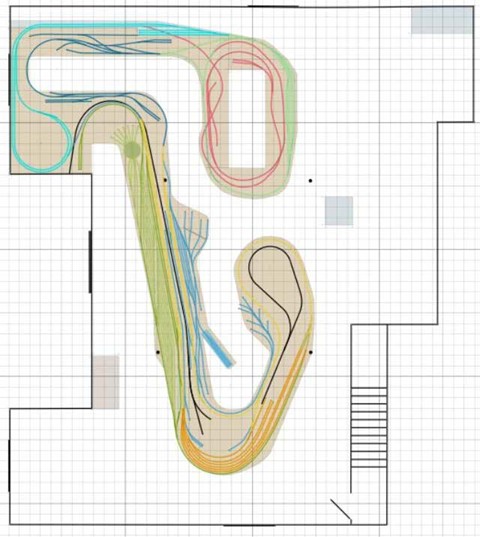
The presentation went on to strip the yard down to the basic elements.
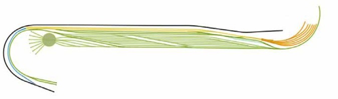
The mainline comes in from the left on this diagram. The yellow lines represent a siding which can be used as a part of the yard or the passenger terminal which is to the right side of the diagram in the orange track diagram. The upper long green tracks are the drill tracks adjacent to the first of two sets of ladder tracks in a diamond formation. These tracks will each accommodate nine cars per track. This is the comfortable number of cars for local freights. Longer trains can be serviced using the longer tracks tying the two sections of the diamond ladders together. The engine servicing area is to the left of the yard including the turntable. The small section of track to right of the yard ladders is the caboose track.
A time lapse of the yard construction was shown with the result as seen in the photo.
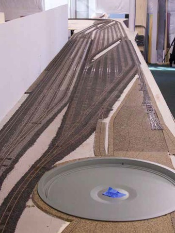
This gives better perspective of the overall yard construction. The rundown of the yard capacity is as follows:
- 3 Arrival/Departure tracks – capacity 24 (40′ cars).
- 6 classification tracks – capacity 9.
- 7 classification tracks – capacity 14.
- 1 classification track – capacity 27.
- 1 runaround track.
- 1 caboose track.
- 1 yard lead – capacity 28.
- 1 yard lead – capacity 19.
- 130′ turntable.
- 52 turnouts.
- Mainline & A/D tracks: Peco #8 turnouts.
- Yard tracks: Peco #6 turnouts.
- Peco code 83 flex track.
- Yard tracks planned to remain manual throw.
- Mainline & A/D tracks will eventually have switch machine control.
With an eye toward operations, the yard should provide interesting work for two and possibly three people. The open tracks will provide room to assemble and block trains for departure. A car card rail runs all along the yard length for ease of sorting. This keeps the cars off the layout or yard. The one track on the edge of the yard is isolated as a programming track. The yard is about half ballasted with Arizona Rock products. The material was to be one color mix but because the product was ordered at different times, the color is varied. One must be mindful and mix the batches to add more uniformity to the ballast.
Scott read many publications and articles on yard design and operations. This is his bibliography:
- Andy Sperandeo: The Modeler’s Guide to Freight Yards.
- Tony Koester: Realistic Model Railroad Operation Planning Your Model Railroad.
- John Armstrong: Track Plannning for Realistic Operation.
- OPSIG: A Compendium of Model Railroad Operations.
- Robert J. Church: Steam Days in Dunsmuir.
- Jeff Wilson: Great Northern Railway in the Pacific Northwest.
- Dale Peterka: The Great Northern Railway Through Time.
- Eugene V. Smalley: History of the Northern Pacific Railroad.
The track was painted a rust color. The use of an airbrush to do this work was his choice and to protect himself Scott has constructed an open bottom portable spray booth. This was inspired by Boomer Diorama, a YouTube modeler with a collection of videos on his modeling technique. As a follow up to the airbrush color, Scott sealed his yard tracks with Mod Podge spray sealant. A portable exhaust fan arrangement was built with a 6 inch fan and dryer vent tubing. The dog door was pressed into service as the outlet for the fan. The results of the filtration were shown with the used filter next to a clean filter and the difference was obvious to even the most casual observer.
February Clinic – February 17, 2025
Clinic – Civil War Railroads
Wally Weart Biography
Wally grew up in Chicago and after college, spent his career in various aspects of Supply Chain Management. Starting in 1992, he moved to Denver and various career moves took them to Virginia and Canada. He returned to Denver in 2007 and during 2009, he became involved saving the .04, the last interurban streetcar to operate in Denver, which will be the subject of a later clinic when the car is released by Cheyenne, Wyoming.
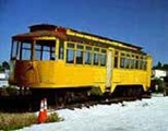
Wally Weart presented his clinic on Civil War Railroads. From the beginning of the Civil War at the battle of Bull Run in 1861 through to the surrender of Lee’s army at Appomattox, railroads were a prominent factor throughout. Early reinforcements at Bull Run allowed the Confederates a victory while the destruction of a supply train at Appomattox Station causes Lee to rethink his strategy. Railroads were central to the War efforts. We’ll not only look at the role of railroads in the War but also the technology of the day.
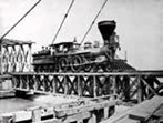
Wally worked for the Gettysburg Railroad as an engineer during its life as a short line. The railroad moved freight for customers interchanging at Gettysburg with the CSX and at Mount Holly Springs with Conrail. It also ran a tourist passenger rail service as Gettysburg Passenger Service. This tourist line was not well received by the rail crews as it interrupted the freight flow during the day. It is important to note that Gettysburg is pronounced “get” “EEZ” “berg” with the emphasis on the second syaballe.
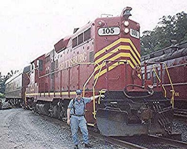
Wally’s interest in the Civil War stems from family history. His great-great-grandfather, John Larrabee, was assigned to guard the Nashville and Chattanooga Railway at the Bell Buckle Creek. President Lincoln was granted the power to take control of the railways and telegraph lines in the interest of public safety.
This was not the first use of railroads during war. The first use was by Great Britain during the Crimean War. The railroad carried supplies and was the first use of a hospital train. While the transcontinental railroad was not specifically related to the Civil War, the War allowed the Union to choose the central route of 5 routes from the Midwest to the Pacific. Railroad manufacturing heavily favored the Union as locomotive plants were located in the North. Rail rolling mills were primarily located in the North. The South built no new locomotives during the war. The North was able to produce over 400 locomotives during the war.
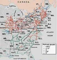
The use of the railroads was confounded by the way the railroads were routed and by the difference in track gauges. The southern railroads were oriented from inland cities to the sea ports. Little interchange was possible as the routes did not intersect, and the track gauges were different. The North had 10 track gauges, but the rail networks were more extensive.
Railroads were purposely built with differing gauges to keep rolling stock and loads on the originating railroad. Richmond was served by six railroads but none of the lines had a connection with any other line. The “T” rail was 35 to 65 pounds per yard. This compares to modern rail at 130 pounds on tangents and 150 pounds on curves. Remembering that the locomotives and the rail cars of the time were lighter.
The southern rail network was hampered by the few major junctions to provide through service throughout the South. The loss of key rail junctions at Corinth, Vicksburg, and Atlanta severed the network and interrupted the movement of troops and supplies.
A significant drawback to the southern rail systems was that the government did not require coordination between the rail lines. The northern railroads were all compelled to coordinate with what once were competing railroads.
The lack of manufacturing capacity in the South had a negative effect on the railroads. They suffered from a lack of maintenance and the inability to construct or repair equipment.
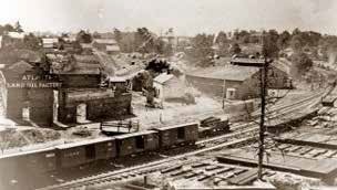
Tredegar Iron Works was a supplier of locomotives prior to the war. It was switched to cannon manufaturing during the war years. The Baltimore and Ohio Railroad was critical to the northern war effort and as such took heavy damage due to fighting along the line. The railroad was located south of the Mason-Dixon Line and was struck by 143 raids and battles.
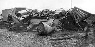
Train crews were endangered by opposing troops and by train wrecks. They were exposed in the cab and had no defensive capability.
Equipment on the railroads were light weight locomotives, 4-4-0 wheel arrangment, capable of hauling 10 cars of 10,000 pounds each. The B&O had some 0-8-0-wheel arrangement locomotives used to haul coal. There were brakes on the tender but none on the locomotive. The locomotives were wood burning which required re-fueling about every 10 miles or so.
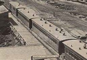
Passenger cars were 41 foot wooden affairs with rounded roofs, and wood stoves at each end. These seated 50. Later cars were expanded to 52 feet long, but still seated 50 passengers. The stoves carried a high fire risk for these coaches. Freight cars for the war effort were flat cars, box cars, and tank cars. These were wooden cars with link and pin couplers, and hand brakes only. So the make up and break down of trains was a risky business. There were a few iron box cars to carry munitions with the iron sides providing some safety from directed fire.
Hospital cars and trains were a necessary part of the war effort as casualties required transport away from the action. The early versions were beds built in standard passenger cars with the improved ride later provided by rubber straps suspending stretchers for a slightly better ride. The hospital trains operated as dedicated trains with the addition of a boxcar to provide meals.
The United States Military Railroads were organized in June 1862. The primary purpose was to operate the railroads captured in the South and utilize them to supply Union troops. By the end of the war the USMR operated over 2105 miles of track using 419 locomotives and 6330 cars.
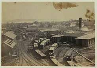
They built or rebuilt 26 miles of bridges. The USMR operated a yard, roundhouse, and storage facilities at Alexandria, Virginia. The area has been redeveloped as a townhouse complex retaining a street named “Roundhouse”. The storage facilities that were located at the site included rail stacks and boxcars for ammunition.
The railroad fielded some offensive weapons. An armored railroad monitor could deflect light artillery. They resembled elongated pyramids similar to ironclad naval vessels.
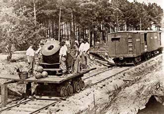
An oversize mortar named the Dictator was used during the siege of Petersberg. This weighed in at 17,120 pounds and fired a 218-pound shell using 20 pounds of power to a distance of 2.7 miles. This shell was the bunker buster of the Civil War.
The effort attracted some personalities to build and maintain the railroads. Herman Haupt was a civil and railroad construction engineer. He revolutionized the North’s military transportation, particularly railroads. He did not accept the military system and found himself relieved of his duties September 14, 1863. Daniel McCollum assumed his duties and role in the War effort.
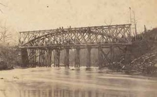
Haupt designed pre-fab bridges to speed the reconstuction effort. These were 60 foot trusses which could be carried to the site and assembled quickly. The height of these efforts was the construction of 5 bridges of varying lengths in one day. Haupt was put in charge of the railroads in the Battle of Second Manassas to correct the supply line situation.
Back to Gettysburg, Haupt was in charge of supplying the Union forces on the Gettysburg single track railroad with no passing sidings or turntable. Haupt fleeted the train five at a time. The cars were unloaded immediately with the returning trains delivering wounded to Baltimore hospitals. By July 3, 1500 tons a day were being delivered. Haupt urged Mead to move after Lee.
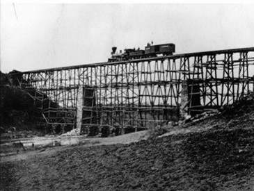
Abraham Lincoln held Haupt in high regard as Haupt constructed a 500 foot long bridge, 100 feet high over Potomac Creek. This was a spindly affair, but trains were able to cross every hour.
To supply the Army of the Potomac, freight cars were loaded on barges at Alexandria and floated to Aquia Creek in about 8 hours. At Aquia Creek, the cars were hauled to Falmouth. This allowed the cargo to be delivered without transfer.
In 1863, Daniel McCallum was appointed Military Director and Superintendent of the Union Railroads as a Colonel. He received a series of promotions finally mustering out of the service with the rank of Major General. His contributions to the war effort were largely focused on efficiency of the service. He was hands-on in his leadership. He was the liaison officer between the government, railroads, and equipment manufacturers. His greatest single success was supporting western operations from Nashville and Chattanooga in support of General Sherman’s army. This was acknowledged by Sherman in his reports.
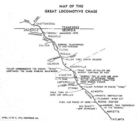
The Great Locomotive Chase was the theft of a locomotive and rail cars from Big Shanty, Georgia by James Andrews and a band of guerillas. William Fuller gave chase and eventually recaptured the train. A Disney Studios movie, The Great Locomotive Chase, illustrates some efforts to control the railroads during the war. The locomotives were authentic on loan from the B&O Museum and the movie was staged on a north Georgia short line railroad.
The First Bull Run or First Manassas was decided when General Joseph Johnson marched his troops from Winchester to Piedmont Station. They were able to board a train that carried the fresh troops into the battle breaking the Union line and allowing a Confederate victory.
Confederate reinforcements were moved by rail to Chickamauga. This is a circuitous route to reach the battlefield by moving through the Carolinas, loading south of Fredericksburg. Hood’s division was first, second was McLaw’s division, followed by Alexander’s artillery battalion. General Longstreet’s veterans arrived at Catoosa Station on September 18th. They moved to the front as they arrived and were followed by the remaining troops. The Union lines were broken giving the victory to the Confederacy.
The U.S. Military Railroad was instrumental in assisting the Union Army of the Potomac’s 11th and 12th Corps from northern Virginia to Chattanooga, Tennessee. McCallum was in charge of planning the movement and using 6 railroads within 14 days, moved 23,000 men and their equipment. The trip took 12 days and covered 200 miles by rail and steamboat. The troops were traveling light, but with full ammunition cartridge boxes.
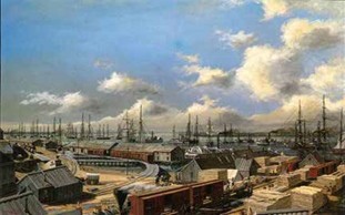
During the siege of Petersburg, General Grant’s headquarters was at City Point, Virginia. USMR workers constructed 21 miles to link City Point with the Union front lines at Petersburg. City Point supplied 100,000 troops and 65,000 animals to the area. Barges carried 25 locomotives and 275 freight cars to City Point from Washington. The construction of the railroad took 22 days and trains were operating on a full schedule. At the maximum use, 18 trains a day were operating on the railroad. No formal stations were constructed but the trains operated between supply depots along the line.
The Southside Railroad was the final railroad severed by Grant at Petersburg. This marked the end of the Confederate hold on the city.
Jefferson Davis and others boarded the last train from Richmond and headed to Danville after hearing from Lee that Petersburg was lost. This travel was on the Richmond to Danville Railroad, one of the South’s most important railroads. The Union forces severed the rail line south to Charlotte, meaning that Davis and others needed to proceed on horseback.
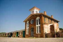
Farmville, Virginia, was a station on the South Side Railroad. Both armies could be found here in the waning days of the Civil War. Lee ordered food railed to Farmville from Lynchburg. On April 7th, the remaining Confederate Army reached the boxcars of food and supplies at Farmville. The Union attacked the soldiers, after dark the Confederates marched to Appomattox Courthouse.
The Battle of Appomattox ended the Civil War on the afternoon of April 8th as Lee surrendered to Grant. Union cavalry captured trains loaded with supplies for the Confederates and later captured General Walker’s wagons and artillery.
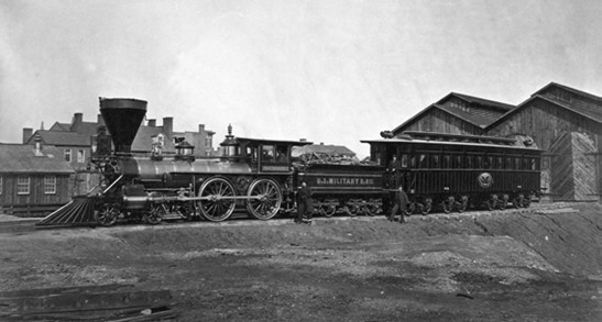
The last train of the Civil War was President Lincoln’s funeral train. This train traveled through 180 cities in seven states to reach Springfield, Illinois. A replica of the funeral car has been constructed.
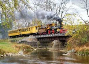
The Northern Central Railway is a tourist railroad operating between Hyde and New Freedom, Pennsylvania. This is a recreation of the railroad that operated between York, PA and Baltimore, MD.
For more information on railroads during the Civil War, see the Civil War Trust video: https://www.battlefields.org/learn/videos/railroads-civil-war.
January Clinic – January 20, 2025
Clinic – My Journey to Modeling in S Scale
Keith Hayes Biography
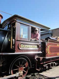

Keith Hayes is a Colorado native who started playing with his Dad’s Lionel trains at a very early age. Many summers reading Model Railroader and studying the plans therein resulted in a career in Architecture. Bill Wardell introduced Keith to Sn3 and when it came time to build a layout, the subject was going to be a freelanced Colorado pike. Choosing Leadville, CO as the subject of the first town has led to modeling the C&S between Leadville and Breckenridge, CO in the 1930s. Keith lives in Denver with his wife and three cats and regularly posts progress of the layout on the C&S Sn3 blog.
Keith Hayes will relate his journey to modeling in S scale, a narrow-gauge layout, the development of standards for the layout, how he settled on a prototype by accident, and some of the discoveries made along the way.
Keith Hayes gave us a look at his journey developing his Sn3 version of the railroads and area around Leadville, Colorado. He models the Colorado and Southern Railway in Sn3. His chosen time frame is the 1930’s. As this is an S scale effort, the buildings and structures are 1:64, this is important as it ties to his architectural profession. Keith dabbled in O scale, but discovered that the buildings in particular are very large. He discovered as he began to pursue his MMR that the required level of detail increased with the larger scale. During the 1980’s, several suppliers of Sn3 rolling stock kits became available. Brass locomotives were imported in a variety of locomotive types. Kits for rolling stock were available from:
- P-B-L
- Tomalco
- Triangle
- Overland
- BLW
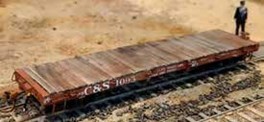
Structure kits were available from Banta and Crystal River. This led Keith to building a P-B-L D&RGW 6500 steel flatcar. But he also brought and constructed a P-B-L long caboose with a full interior. This was a challenge.
This journey continued into the layout standards. What minimum radius should be considered for his layout?
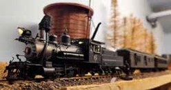
After a good deal of research, the minimum radius was set at 30 inches with #6 turnouts as a standard. Given the circumstances, he wishes he had used 32 or 36 inches as the minimum radius and set the turnouts to #7. “Bigger is better.” Once the track parameters were set, it was time to review the design train lengths. As the passenger trains have longer cars, he designed the track plan to accommodate a 60 inch long passenger train. This appeared ideal, but the design train should have been about 36 inches long in fitting with the 1930’s time frame. Further, the freight train design was for 96 inches in length and again this was too long and should have been 76 inches in length. The common locomotive was 2-8-0 and the model will pull 4 cars on a 4% grade. This looks realistic and double heading the locomotives gives a nice train.

The track plan was the next item on the development path. Several model layouts were considered, and Dave Adams’ plan was one that was most appealing. The features that needed to be on the layout included a roundhouse, neat brick depot, water tank, wye, and coal trestle. Not all of these could be found in one town along Colorado and Southern Railway. The layout can be termed a “greatest hits”. So, after reviewing modeling efforts of others and the Colorado environment, Leadville came out ahead. It had three of the five desired elements. The roundhouse, depot, and a wye were all there. This led to a model railroad from Leadville to Breckenridge. The layout is a two-level endeavor with the signature scenes of Leadville and a helix to a lower level with Breckenridge. The helix is under construction and the hope is to finish that in 2025.
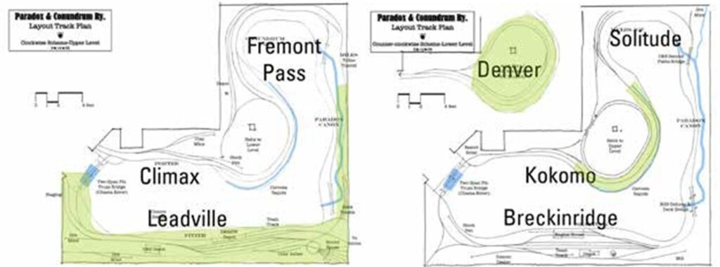
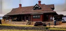
To bring this together, the Leadville depot was modeled using laser cut wood brick sheets, dormers are 3D printed parts, the windows and doors were 3D printed, and the roof is a styrene sheet assembly covered in Wild West shingles. This is a signature piece on the layout.
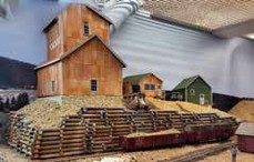
The Penrose Mine is in the area of the depot and serves to distract attention from the real-world plumbing.
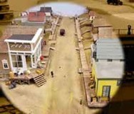
Based on photo research of 1930’s Leadville, Hemlock Street was the focus. The layout features the scene with on the outside corner of the street beginning as S scale width tapering to N scale width at the backdrop. Using various scale structures in a similar fashion, the street appears longer than the 20 inches. At the corner of Hemlock Street is Dunn’s Buns, Pies, and Cakes which is a Silver Plume Bakery model with interior furnishings.

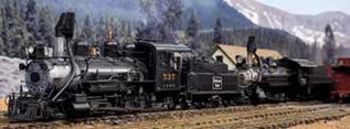
CB&Q number 537 is a locomotive that seemed out of reach until it became available, and Keith was able to acquire the model. This was a locomotive leased by C&S in an effort to meet the freight commitment. People on the railroad are always in demand. Keith uses a simple military modeling technic of painting the model all in black and spraying the figure from above in white. Using acrylic dilute washes to color the model. The highlights show through and add variation to the model not normally achieved with more dedicated painting technics.
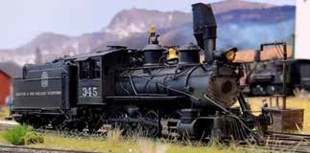
D&RGW locomotive 345 was another lease unit used in freight duties. Keith modeled a 3D printed head end baggage/mail car with unusually arched windows and doors. This body was printed in 3D, and the frame, underbody, trucks, and other details were modeler supplied.
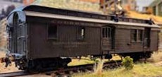
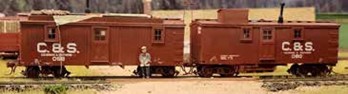
Keith also showed a couple of maintenance of way cars that were patched out Denver, South Park and Pacific Railway cars renumbered for the Colorado & Southern. He used aircraft modelers’ technic of painting the car, painting patches on the car of the white and black areas and repainting that with a light coat so the coloring was still visible. The C&S lettering was applied over the patched areas. Added to the cars are chalk marks. The one car is loaded with materials on the roof, including rope and pipe.
One of the juried cars for his MMR achievement award was a C&S flat car built up of styrene shapes filled with tungsten putty for weight. The deck is a ship lapped wood deck for realism.
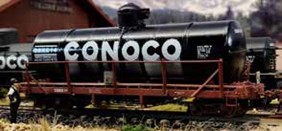
Another car is the Conoco Oil tank car which is a privately owned car. The tank is placed on a flat car with angled out railings on the side. This was a 3D printed car with details added. The railing was fabricated from brass strip and rod. The last car built for the achievement submission was a flanger. The flanger was basically a Rio Grande design, just a shorter car. The frame was a 3D print with brass detail parts to complete the operating model. The blade can be raised or lowered with the brass mechanism.

The last bit of information is on British sourced figures that are plausible stand-in of 1920-1930’s U. S. workers with a variety of hat styles and differing clothing. See the catalog at: https://www.modelu3d.co.uk/.
Lessons learned from Keith’s model railroading journey:
- Don’t let fear get in the way of progress
- Set reasonable standards – don’t go small
- Less is more
- Be patient
- Lean on friends for advice and new techniques
- Challenge yourself, have fun
One final note: Keith Hayes has passed the AP Cars evaluation and will soon receive his certificate. Congratulations!
Clinics for 2024
December Clinic – December 14, 2024
To see commentary and picture for the Gathering of the Elves, click here.
Once again, the Front Range Division holiday party will be held at Rich Gibson’s house for the Front Range Division and Flatirons members and guests. Please save 6 PM onward, Saturday December 14 for this event. For this event, Janet and Rich will provide enchiladas and a limited selection of beverages. Please plan to bring a potluck dish to share and any specific beverages that you might prefer.
If you plan to attend, please reply to richgibson89@yahoo.com with the number of festival attendees and what potluck dish you intend to bring. If anyone is a vegetarian or gluten free, also include this info so food can be planned accordingly.
November Clinic – November 18, 2024
Clinic – Advanced Tools & Tips
Doug Geiger Biography
Doug lives in Longmont with his wife Barbara and their cat Foxy. Other interests besides model railroading (which he lives and breathes almost daily) includes submarines, science-fiction books, and travel. He was born in Montana, lived in Houston (where he obtained much of his model railroad knowledge) working for Shell Oil and moved to Colorado in 1981. He retired in 1991 and became a househusband.
Doug Geiger, MMR, presented his clinic on Advanced Modeling Tools. A number of the tools and tips within the clinic come from the International Plastic Modeler’s Society. This group is an organization for the military and ship building practitioners that largely model alone with some modeling contests to judge their work. The modelers have advanced technics and specialized finishes.
Tools can easily be the most important part of enhancing your modeling skills. Join us as we explore various modeling tools and supplies, ranging from advanced (for example, calipers and material organization), moving to exotic (punch and die sets and scribers to name just a few), and concluding with some power tools (slow speed drills and mini Sawzall’s for instance). Many of these tools are not often seen in the model railroading world but are used extensively in the IPMS world (International Plastic Modeling Society – those folks who build airplanes, armor, cars, and ships). Modeling tips using these tools will also be discussed during the clinic. Some of the tools will be passed around for you to handle. Some of the more exotic supplies will also be discussed.
Doug started off by showing his work surface. This is a piece of annealed glass about ¼ inch thick and of a comfortable size for the workbench and modeling scale. This is best obtained at a local glass shop by requesting a piece of scrap material in a general size range.
The tool list is as follows:
- Irwin pistol grip clamps – source from Home Depot or Lowes on special.
- Rite-Way clamps – These are right angle clamps that are held in place by strong rare earth magnets. Walthers has these and other hobby shops carry them.
- Marking pen – This is a Micron 005 fine tip pen. The tip is 0.20 mm in diameter. This can be found at art supply stores and online.
- Flex-I-file – A flexible abrasive band held between the ends of an aluminum frame for sanding curves. Doug has bent one of the frames at 90 degrees to rest on or be clamped to the work bench. He also marks the grit number on the frame for best identification. This file can be sourced at https://flex-i-file.com/ or at hobby shops or other online retailers.
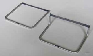
- Razor saws – A better razor saw is found at www.umm-usa.com or lately from Micro-Mark. This has more rigid blades and holder for more precision cuts.
- Parallel nose pliers – These are compound action pliers that hold the jaws parallel throughout the motion. These are useful to snap styrene after scribing. These can be found at Micro Mark, Amazon, or other hobby stores.
- Scalpel – A fine tool for working with decals. This tool is reserved for decal work only. Some may be sourced at Micro-Mark or Amazon for a wider variety.
- Cleaning a CA applicator – Use a candle to vaporize CA out of the needle style applicator.
- Drills smaller than number 80 – https://www.travers.com/product/sphinx-spirec- cobalt-micro-twist-drills can be found at Travers Tool as a Sphinx brand. The drill sizes start at number 92 and go to number 80. These are expensive drill bits but if you need a smaller hole you can get it done. Other small drill bits are available in metric sizing online.
- Small parts holder – These are alligator clip sticks with a model stand base holder. They can hold the parts for gluing, assembly, or painting. The better models have PVC coated clip ends and a magnetic base for securing the sticks. These are available on Amazon and eBay.
- Large circle cutter for styrene – This is a compass with a sharp blade to scribe the circle around a center point. This tool is available at Micro-Mark.
- Shear rise cutter – This is a Xuron end nipper. The cutting action is at the end of the tool jaw, and it cuts flush on the end. Very useful for trimming ends of stirrups or grab irons. This tool is available at Micro-Mark.
- Dspiae Mandrel – This company makes a number of small tools. The mandrel allows repetitive curves in brass or aluminum. This can be found at: https://dspiaestore.com/ .
- Samawangu Panel Line Scriber – This is a set of chisels that allow scribing of lines in styrene without the resulting ridges on each side of the line. These are used against a straight edge. These can be found at: https://www.thehobbystore.my/products/ or alternative sources.
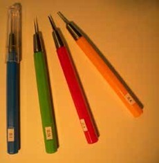
- Zona Knife Holder – This is an alternative to an Exacto blade holder. The holding tube extends through the handle and allows a secure hold to whatever blade is in the chuck. This is available at: https://www.zonatool.net or through Amazon.
- Micro Shears – This scissor is commonly used for model ship rigging. It is a small closely set scissor for close work. These can be found at Amazon as Modelcraft micro snips or at hobby shops with a wide selection of ship building supplies.
- A paired tool tip – Hot Glue Gun and Hot Air Gun. When you use the hot glue and get a mass of stringy glue pieces, use the hot air gun to heat the masses and the glue will disappear.
- World War Scenics Static Grass D-Baller Box – This is an English product assembled from laser cut plywood parts that a modeler may use to separate static grass fibers that have formed balls during use. Amazingly, this product can be found on Amazon plus shipping, or ordered from https://www.wwscenics.com/ from the U.K..
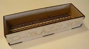
- Wheelset Spreader – Spread the truck side frames to allow the wheel sets to be removed or installed. This has been an HO only product from Micro-Mark, but they have brought out an N scale version, SKU 90799. This is a real time and finger saver.
- Touch-N-Flow glue applicator – This is a glass tube with a hypodermic needle at the end for applying solvent cement. Great tool for controlling the glue in joining styrene parts. One fills the tube with a plastic bottle fitted with similar needle. This is a Flex-I-File product, so it can be sourced at those dealers.
- Micro Reamers – These are essential to open holes in parts that have paint or have been drilled a bit under sized for grab irons, stirrup steps, or ladder standoffs. These are available at Micro-Mark.
- Digital Camera – This is an essential inspection tool. Take a photo of the work and observe for any flaws.
- Exacto Blade Saws – These were originally cut into No. 11 blades, but are now available from Micro-Mark as a laser etched blade that will fit a handle. This is for sawing in confined spaces or around obstructions.
- Grabhandler Grab Iron Maker – This is a jig to be used to bend grab irons or stirrups to fit the model. Since it is a jig fixture, the modeler may repeat the process as necessary. This tool is available from Walthers.
- Electrical Component Lead Bender – This is a companion product to the Grabhandler. This tool allows the modeler to bend sharp bends in electrical component leads. These can be found online.
- Photo Etch Bender – This is a larger jig made to bend photo etch parts sharply. This is best used with the supplied straight edge or a similar straight edge for a sharp uniform bend in the part. These are available from Micro-Mark or Amazon.
- Strip Maker – The Monokote Smart Stripe Maker is a rotating drum filled with material to cut into strip. As the drum rotates, a number 11 blade can slice off a strip to the desired width. This provides for unusual width strapping or tie downs that need be modeled. These machines may be found on eBay.
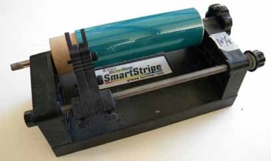
- Large Punch and Die Sets – These are sets using a sized punch to make holes or rounds in thin material. These were used to make gaskets in early automotive work. The material to be cut is placed between two machined dies and the punch is driven through the material by a rubber mallet. (Editor note: A dead blow hammer works best for me.) These can be found at Micro-Mark or Harbor Freight and other outlets.
- Mini Punch and Die Sets – This is a smaller version of the punch and die set. This can be found at: Unique Master Models – www.umm-usa.com.
- Micro Punch and Die Set – This is the smallest version and is meant to punch out small discs down to .018 diameter. This can be found at: Unique Master Models – www.umm-usa.com.
- Miniature Sawz-All – This is a small version of the big tool. This can be found occasionally on eBay or at hobby swap meets. This tool is great to cut plaster castings.
- Miniature Power Miter Box – This is a Micro-Mark tool that functions as a mini version of the power miter saw. This can cut bigger square tubing or stock to length or at a mitered angle.
- Minicraft Slow Speed Drill – Minicraft is a British company that supplies a number of modeling tools. This is a variable speed drill that allows one to cut holes rather than melting a hole. It will get down to 2 RPM. The chuck will handle a No. 80 bit. The tool can be held like a pencil.
- Micro-Mark Micro Sander – This tool is a miniature vibrating sander with various shaped attachments and sand paper to match. This can get into small and odd shaped spaces. This is much better than hand sanding.
- Laser Cutter – This is another tool for modeling. This tool can be the subject of another clinic. This is an outdoor tool.
The next portion of the clinic is the supplies that are not as common. The supplies include:
- VMS Super CA Glue – This is a family of CA glues with super strength. A unique member of the family is black CA. The black comes from a small amount of rubber. This is useful as you can see where the CA is to sand the excess off. You can sand CA off if it is within the first 10 minutes or so. These are available from Michigan Toy Soldiers – www.michtoy.com.
- Thinning super glue – Modelers can use Plastruct Bondene to thin, thick CA.
- Tricky Stick – Allows CA to bond to slick plastic, such as, truck side frames, or handrails. This product is available from Michigan Toy Soldiers.
- Canopy Glue – This product dries clear, so it is less visible and will not fog clear styrene. Not a strong bond but good for small parts.
- Beeswax – Use this on thread to make cables or rigging. This can be found at most hardware stores or home supply centers.
- Soldering Paste Syringe – Use a syringe for applying flux right where you want it. The flux can be stored in the syringe with no harm.
- Wine box for strip styrene storage – Save the box and use the divided space to store the packages upright.
- Pan Pastel Carrier – Using the carrier that the pan pastels are sold in, glue the base to the carrier with a little CA. Make a mark on the carrier and the lid of the pan pastel to match up the closed container.
- Rolling stock weights – Buy shotgun shell pellets for use as weights in rolling stock. Again, use CA to anchor the shot within the model cavity.
- Dedeco Cutoff Discs – These are fiber reinforced cut off discs or extremely thin discs. The fiber discs are very strong and will resist a good deal of side pressure. The extremely thin discs are very thin and can make fine cuts. These are available from: https://www.dedeco.com/.
- Tamiya Body Putty – This is the preferred body putty for models.
- Vallejo Acrylic Putty – This putty is not solvent based and can go into thin openings to seal the surface. This is not a sand-able product, so it goes on thin and stays thin.
- Molotov Chrome Pen – This is the traditional product for chrome finishes on models. It is a silver paint pen.
- AK Interactive Paint Pens – The set is available with a wide selection of colors. These are easy to use and do an excellent job for small area painting or touch up.
- AK Interactive Splatter – This is a two-part splatter tool and splatter finish. One uses the tool to splatter the finish onto the model surface. This is useful in railroad modeling to make stucco or plaster finish on the model. The material can be painted any color when dry.
- World War Scenics Layering Spray – This product is for layering static grass. The modeler can start with a 2 mm grass, move to a 4 mm grass, and finish with a 1 mm grass. Use the layering spray between grass applications and the material is fixed.
- Woodland Scenics Water Effects – This material is just caulk with differing viscosity.
- AK Interactive Asphalt – This product is used for paved surfaces on the layout. They also have concrete in a jar, which is a similar product. After the product dries, it can be sanded or rubbed to create the used asphalt look and coloring.
- Coastmans Forest Products – A family of two products that are used for forest floor litter and downed timber.This is natural material and can be anchored with matte medium. This gives the appearance of the cluttered forest floor. These products and more forest scenery can be found at: https://www.coastmans.com.
- Tamiya Tape for Masking – These tapes are flexible to seal into cracks for a crisp paint line.
- Archer Rivet/Weld Bead Decals – Microscale decal paper with rivet or weld patterns on the sheet to be trimmed and applied to the model surface. After application, the model can be painted, and the thin film is not visible on the finished surface.
- Decal Setting Solution and Decal Repair – Use liquid decal film to coat old decals and make the material useable again. Tape the yellowed decals to the window for about two weeks. The yellowing will have faded, and the decals will be useable.
- Mr. Surfacer Primer – Primer everything. There are several products including a brush application for seams, a thinner to feather the edges of seams; and primer airbrushed on at 4:1 and 10 psi. These products can be found on Amazon, eBay, and military-focused hobby shops.
- Vallejo Model Air Paint – This paint is available in two types. The model air is ready to airbrush, and the model color is brush paint. The colors are identical between the two product lines. The Micro-Mark colors are the same material.
- Tamiya Panel Line Accents – The material was developed for aircraft modelers. The applicator is very tiny and can follow the expansion joint lines very well.
- AK Interactive Weathering – This is a spectrum of weathering colors. They have an engine oil material that appears wet even after drying.
- Turpenoid – Use this to clean up after using solvent based finishes.
- VMS Chip & Nick – These products are applied to painted surfaces that have been gloss coated. Apply the chip & nick colors over the surface, after about 15 minutes, scrub the surface with a stiff brush moistened with tap water. The material forms little chips on the surface. The more the surface is worked the more the effect is removed. This is available from Michigan Toy Soldiers.
- Diesel handrail paint – Testors Racing Finish paints are used by R/C car modelers to paint the car bodies which are made of a similar material to the model diesel handrails.
- Tamiya Clear for Decals – Use the Tamiya Gloss paint and thinner for coating decals.
- Model Master Flat for decals – Use this for flat finish over decals.
- Vallejo Acrylic Metal Color Paints – They make a variety of metal look finishes to add the base metal look to models.
- Alcald II Metal Paint – Best look for metal finish. This is used by aircraft modelers for metal finish. This product must be applied over a glossy black finish for the best effect. This is available on Amazon, eBay, and at hobby stores specializing in aircraft modeling.
The Division wishes to thank Doug for sharing this knowledge base with the group. There are a lot of products and technics that we can try on our continuing modeling projects.
October Clinic – October 21, 2024
Clinic – “How Did We Win the War in Europe, Grandpa?”
Gerry Glancy non-Railroad Biography
This is a story that Gerry, as usual, stumbled into while researching hospital trains. Military success in Europe in the Second World War was largely dependent on logistics; i.e., having enough ammunition, fuel, and food for the troops at the right time and place. Unbeknownst to Gerry, the success of the European Campaign was largely due to the rapid restoration of Western European railroads. They had been largely destroyed prior to D-Day by a combination of Allied airpower and each country’s clandestine underground organizations. It’s a fascinating story of planning, training, innovation, and determination in the face of a constant hostile environment. Besides the usual challenges of destroyed railroad infrastructure, cut communications, and downed bridges, the troops had to deal with the Schienenwolf, the rail wolf. Had the Allies failed to restore the railroads effectively, the military success in Europe would have been either greatly prolonged or in doubt.
“Born, raised, and educated in California, fortunately in an era when public schools were high quality and enjoyed wide public support. Graduated from medical school in 1966 at which time (Viet Nam) a special set of laws covered physicians. Most new graduates faced a two-year military commitment in some form or another. So, he signed up for two years to “get it over with”. Fourteen years of active duty later he was still “getting it over with”. It was the US Army that sponsored his training in pediatric orthopedic surgery. Finally deciding geography was more important than furthering his military career. Gerry settled in Denver and joined the staff at The Children’s Hospital. Ironically, he retired from the same location where he trained in orthopedics, Fitzsimons. Now watching seven (7) grandkids grow up with the satisfaction of knowing that he can facilitate some of their adventures, including model railroading.”
The Clinic took a look at the European Theatre of World War II (WWII) from D-Day to the the German surrender in 1945. The four elements of war were examined to find the key to the Allied victory. The Allies and Axis Powers were closely matched in the personnel, intelligence gathering, and planning & operations. The area of most divergence was logistics, that is the delivery of supplies to the area of battle. One example was sited concerning a German captured American cake. This cake was in a supply convoy which was captured by the German troops. The question was asked, “How did the Americans do this?’.
The German troops were waiting days or even weeks for basic supplies. The Allies were supplied by deuce and a half trucks, with a capacity of 2-1/2 tons. It was a 6×6 truck meant for rough terrain and uneven ground travel. This was not a comfortable ride. Three million tons of supplies needed to be delivered during the war. This can be compared to the Germans who relied on horse drawn wagons for delivery. They did have trucks but gas was in very short supply. The Germans did rely on the railroads to supplement the delivery scheme, powered by coal. Prior to D-Day, the railroads were bombed to stop these movements. The French Resistance was utilized in sabotaging the rail systems. The rail workers were further recruited to damage rolling stock and misroute trains. The back shop workers furthered the destruction with metallurigical mischief in the forging of rods and pistons. These actiivities forced a 60% reduction in rail travel. The success of the operations required the rapid restoration of railroads and the transportation infrastructure.
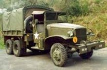
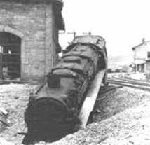
The U.S. railroads were very helpful during WWII to avoid a repeat of the nationalization of the railroads during World War I. The Military Railway Service was established and Railroad Operating Battalions recruited from the major railroads. The Battalions were trained at Camp Claiborne, Louisiana, where railroaders were turned into soldiers and soldiers were made into railroaders. The highlight of the training was the graduation by blowing up your recently constructed bridge.
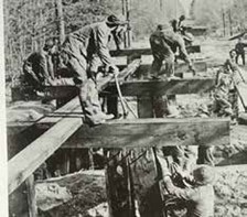
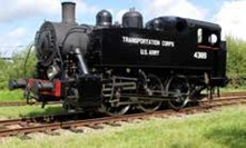
In parallel to the railroad training, equipment was developed to send along to Europe. This included the S-100, meant to resemble European locomotives, Austerity class 2-8-0 locomotives, and first generation diesels. The rolling stock was pre-fabricated in the U.S. with final assembly in Great Britain. The British had added their efforts in the railroad war along side the U.S. conterparts.
In a side note to the European conflict, the Russians were supplied through Iran from 1941 to the end of the WWII. The British and Russian troops invaded Iran, desposed the Shah, and placed a new leader in the country. In a spirit of cooperation, the U.S. entered into an agreement to run the Iranian railroad for the duration of the war. This netted Britian and Russia access to Iranian oil and refineries.
D-Day finally was upon us. The landing was on the beaches of Normandy, but one of the first objectives was a deep water port for supply. Cherbourg was such a deep water port located west of the landing beaches. The military railway service landed soon after D-Day and set about accessing damage, repairing the railroad, and getting the end of the line as close as possible to the front lines. Emerson Itschner was in command of the military railway service and directed the transportation efforts. The railroad efforts were impeded by mines, snipers, and artillery fire. The changing front lines were always a hazard to the railroaders. Repairs ranged from easy track repair to extensive repairs near roundhouses and stations. Cherbourg was finally reached after 21 days. The rail facillities were largely intact, but the port facilities were badly damaged. Supplies were being delivered to the beaches but were not moving off the beach. The LST’s were landing tanks and trucks. The troops modified the ramp to accept railcars. The ramp was the brainchild of Sidney H. Bingham. The tracks were laid on the beach in fast setting cement at low tide. As the tide rose the ramps could follow the tracks up the beach.
The Allies worked to get the French railroaders engaged in railroad operations. Most were reluctant to help, remembering the bombing. Using U.S. supplied goods, the railroaders were recruited to continue work. The recovery efforts were slow. Locomotives and rolling stock repair was difficult. The routing for trains was often
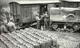
rather indirect. The biggest obstacle was communications. The lines were often cut. Signalling was done by flashlights and cigarette lighters. Bridges were out all along the rail lines. A temporary replacement bridge was developed by Donald Bailey. This Bailey Bridge was constructed of Erector set style components that could be handled by six people. By combining sections, the resulting bridge could span varying lengths and loads. Over 3000 total bridges were used during WWII. Breaking out of the beaches meant breaking through the hedgerows used to define the fields. These embankments were about 5 feet high and covered in mature trees and brush. Sgt. Curtis Culin developed rippers to add to tanks built from the steel hedgehogs off the beaches to break through the hedgerows. This speeded up the transit process and sent the Army on the way.
The Allies were closing in on Paris, but the railroads could not keep up. The idea of the Red Ball Express was borne out of necessity. The trucks were assembled from all the various elements and loaded on a trip to the front lines. The vehicles moved on one-way routes with no interferring traffic. The term Red Ball has a Atchison,
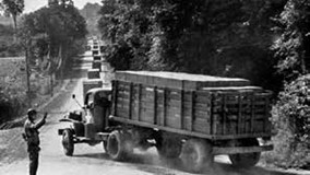
Topeka, & Santa Fe Railway origin as the special handling, high value freight. Ultimately, not even the trucks could keep up with the needs. Liege, Belgium was liberated in September 1944. This was an important railroad junction. The nearest deep water port was Antwerp, and it was the largest in Europe with 900 warehouses, 495 storage tanks, and 625 cranes. General Montgomery diverted resources in an effort to take the German industrial heartland. Back to Antwerp, the Germans mined the Scheldt Estuary and cut off Antwerp from the sea. The Canadiens engaged the Germans on this estuary, and it took a month to clear the way. Germany unleashed the V-1 Buzz Bomb on Liege and Antwerp. When this was not effective enough, they used the V-2 rocket. This was silent and caused a lot of panic. These continued until the launching facilities were taken.
One of the intelligence failures of the Allies was the Battle of the Bulge. The Germans moved 400,000 men and 1400 tanks by moving at night under radio silence in bad weather. The food was prepared on charcoal fires to minimize smoke. The railroad effects of this action was the loss of 225 miles of line, bridges destroyed, and a train behind German lines. The train retreated.
The armies finally got to the Rhine River and proceeded with the same process. Rebuild bridges, restore rail lines, and utilize German railroad equipment. The retreating Germans used the Schienenwolf Rail Ripper to destroy ties and tracks. This was used extensively on the Eastern Front.
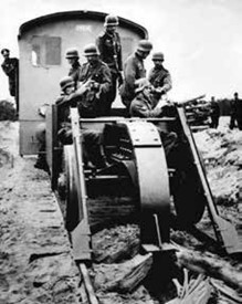
A doddlebug style locomotive was used by the U.S. Army after it was captured.
Hospital trains were used to transport the wounded. The French boxcars were used initially carrying 40 men or eight horses. Later, British hospital cars arrived to carry the wounded. Ambulances were only carrying the wounded 25 miles before rail transfer. This meant the trains were close to the front lines to pick up the passengers. Forty seven hospital trains were in use in 1945.
The war in Europe involved 2,052,099 men and 3,089,259 tons of supplies along with the 3000 Bailey bridges. So, how did we win the war? Rapid restoration and utilization of the railroads.
September Clinic – September 16, 2024
Clinic – Programming Sound Decoders
Gary Ratay Biography

Gary and his wife Nancy, while not being native Coloradans, have been here over 65 years. They recently celebrated their 50th Wedding Anniversary in May. They enjoy travel, with Nancy doing genealogical research while Gary follows the tracks to the trains.
Gary started out looking for a degree in Electrical Engineering but ended up with a Bachelor of Fine Arts with an emphasis in photography. Then taught Art and Photography before getting a Master’s Degree in Library Science and working in school libraries until he took on a technology support position until he retired.
Through the 70’s, Gary, in addition to his teaching, worked for a local film production company as a sound engineer on a part-time basis. In addition to his photographs being featured in exhibits and winning awards, including from the National Railway Historical Society, he has many photographs in private collections in the US and overseas.
Gary Ratay presented his clinic on “Programming Sound Decoders”. Since Gary models in European N scale this offers unique challenges in Colorado. You cannot just go to a museum or rail side to capture the locomotive sound files.
In considering working with sound there are two aspects. Volume versus the quality is the first element of sound reproduction in model equipment, and the second is quantity versus quality. Most available decoders are too loud which leads to overwhelmed senses and adds in noticable distortion. Currently there are three ways to obtain sound equipped locomotives:
- Pre-equipped model
- Pre-loaded decoder
- Upload sound files to suitable decoder
To add sound you will need several items to effect an installation in a locomotive.
- Tools for disassembly and reassemby of the locomotive
- A decoder, speaker, and speaker baffle
- A suitable decoder programmer
- Patience and more patience
Under the tools category, we will find the need for not only the common tools but also test clips, multimeter, DCC decoder tester, the decoder programmer. For his particular needs, Gary finds the products at: https://sbs4dcc.com/. They feature both the ESU and Zimo decoder programmers.

To round out the needs for programming your decoders are cables, software, and other miscellaneous bits and pieces to get everything to work together. Sound decoders are available from numerous companies, including Digitrax, Soundtraxx, TCS, Bachmann, Piko, Zimo, and more. The focus of the presentation was the LokSound and Zimo decoders. Zimo has the smallest decoders including one that is ½ inch wide by 0.4 inch long and 0.1 inch thick. This is important for N scale installations. LokSound offers a Kato style board decoder that is flat. There are no components or protrusions on the underside of the board.
Additionally, one will need a speaker and a baffle. This is the difficult part of the equation as one must locate an area in the locomotive to mount both components. Speakers can be sourced from aliexpress.us, mouser.com, digikey.com, sbs4dcc.com, and ebay.com. The best buys are normally from mouser.com. Available separately are the baffles which are normally termed “sugar cube baffles”. One can make their own baffles using silicone sheeting or plastic. It must be airtight.
To focus on the installation of the decoder, the LokSound decoders were used. They offer simpler software and importantly the LokSound V5 is fully open for adding or modifying sound files. LokSound Select decoders are intended for the American market and only will allow loading LokSound sourced sound files.
For the project, the locomotive is the Arnold 2456, manufactured from 1979 – 1990. This is a four-pole motor and not DCC equipped. The original motor was swapped for a micro motor. The decoder is chosen to round out the project either a LokSound or a Zimo decoder. The sound files need to be obtained from the respective web sites.
https://www.zimo.at/web2010/sound/tableindex_EN.htm
https://www.esu.eu/en/downloads/sounds
The sound file was available from LokSound for the exact locomotive.
The sound file and decoder choice can be an iterative process, where certain sound files are available from one manufacturer and not the other.
The speaker placement needs to be planned out. The location within the locomotive is not that critical. The location chosen must fit the speaker and the baffle. The frame will need to be machined to fit the assembly. Proceed to wire in the decoder and speaker. Test the locomotive to see if it runs to your liking. Some adjustments of CV’s may be necessary to get smooth operation.
There is a choice as to when the sound files are loaded into the decoder. Using the tester and the programmer, the sound files may be loaded into the decoder. Or after installing in the locomotive, the sound files may be loaded using the programmer on the test/programming track.
The next locomotive that was sound equipped was a Kato Lemke K10822 diesel EMD Class 66. This is a specialty locomotive designed for use in Great Britain on low clearance tunnel tracks. It found its way to the continent. The locomotive has little clearance for the decoder and speaker. The LokSound 58741 Kato decoder is a low and narrow decoder. It has built-in resistors for the lighting functions. The LokSound file S0228 matches the locomotive sounds.
Additionally, a Mehano TS513 Vossloh Diesel G2000 model was modified with a Zimo MS500 decoder and the Zimo ZSF01442.
This rounds out the hardware installation examples, and we move into the software portion of the installation. Again, the question is how to add the sound files to the decoder prior to the install or after it is in the locomotive. With the decoder in the locomotive, one can use the programming track connected through the decoder programmer, primarily the LokSound programmer. The PC is connected to the programmer with a serial cable. The programmer is independently powered with a separate power supply. Pay particular attention to the polarity on the programmer and power supply for a match.
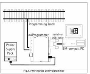
With the decoder outside of the locomotive, one may use the decoder programmer connected to the decoder test board and decoder for programming. One will still need the PC connected to the programmer for transfer of the sound files and CV modifications. Gary demonstrated the locomotives’ operation on the test track. The addition of sounds to the decoder requires that an empty sound slot is available for the modeler to load sound files. In Gary’s instance, he added a bell to the locomotive. The Mehano Vossloh Diesel Zimo decoder was equipped with a false start sequence. This is where the starter attempts to bring the locomotive to life but fails. Stepping through the LokSound series of decoders the higher numbers allow more sound slots for the user. The LokSound 1 has fewer sound slots than a LokSound 5 decoder.
Of note, ESU’s U.S. headquarters is now located in Colorado Springs. It is important to recognize that the decoder programmers are manufacturer specific. The DCC system is not used during the programming activities. The programmer replaces the DCC system for programming and the DCC system is used for operating after the programming and installation is complete.
Gary played a video from the LokSound website: https://projects.esu.eu/ , which showed the selection of sound files for a specific locomotive. The importance is that this information on how to set up the sound files on the decoder is available to the user. Gary demonstrated the sound from a bare speaker. The sound was weak and seemed small. By adding a silicone sheet cover to the speaker, the output was greatly increased. Finally, by adding the baffle, the sound was much fuller and volume increased. The lesson is that a baffle is very necessary and needs to sealed within the locomotive.
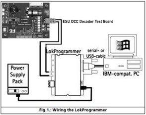
A question was asked about the use of the programmer and serial connector. The manufacturer serial connector was not working, so Gary utilized an old connector from a previous generation and the substitution was successful. It was clarified that the speakers used are 8 ohm speakers. The website, https://sbs4dcc.com/ , has a lot of the products that were used and further, the owner has been very helpful in answering questions on the installations. This is a suggested vendor. He will install sound files for you on the decoders. This eliminates the need for the programmer and hookup. You are not able to further modify the sound file but the upload of the sound file is completed.
With the programmer and setup one can add to the sound files on a decoder to add the startup sequence for example. One can also develop background noise or station announcements to a decoder to play as the railroad is operating. The sound files are .wav files. Gary thanked everyone for their patience, and the Front Range Division thanks Gary for giving us this clinic.
August Picnic – August 25, 2024
The Front Range Division Picnic was held on August 25th at the Colorado Railroad Museum Pavilion. This was a well-attended event with the participants enjoying the potluck offerings along with the centerpiece fried chicken and cold drinks. The food was tasty. The attendees were able to converse on a variety of topics including their recent excursions both railroad and family related.
The Front Range Division wants to thank all for the food to share. Thanks also to those who assisted in setting up the venue and for the clean up afterwards. Be certain to thank Rich Gibson and Janet Schweitzer for the hosting duties!
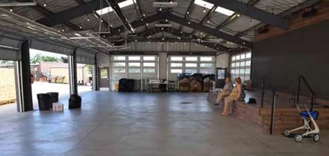
Residents of the CRRM nearby the Pavillion
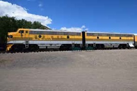
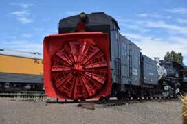
Garden Railroad in Action
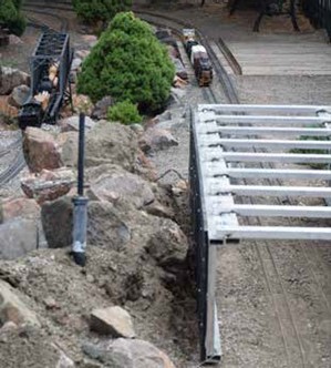
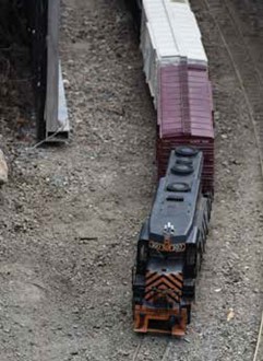
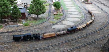
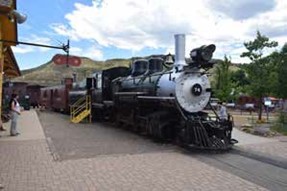
July Clinic – July 15, 2024
Clinic – How Fred Harvey Opened Up the American Southwest

Christine Petty Biography
There are some people who had a major influence in opening up the American Southwest. Fred Harvey, an immigrant from England, was on of the major influencers, along with his son, Ford Harvey. After arriving in America, Fred Harvey started as a pot scrubber in New York City. From there he built a family empire with an emphasis on fine dining and fine service with train travel. Fred started his business with a handshake agreement with Charlie Morse, Superintendent of the small upstart AT&SF Railroad. Later, with Ford Harvey’s business acumen, the empire expanded with iconic hotels and introducing the wonders of the American Southwest to tourists worldwide.
Fred Harvey operated the dining halls and hotels for the Santa Fe Railway. At the height of the operation his establishments could be found from Chicago west to Los Angeles and south from Chicago to the Gulf Coast. He developed an innovative approach to dining rooms and lunch counters mainly catering to the rail traveler.
Fred Harvey was born in 1835 in London, England. He immigrated to the United States in 1853 and by 1858 he had partnered with William Doyle in a dining saloon and restaurant. His primary responsibility was the restaurant in this establishment. In 1859, he returned to England, returning to the U.S. with his father, sister and a Dutch wife Ann. In 1861 he joined the Confederate Army. At the urging of a friend, he relocated to St. Joseph, Missouri and was hired by the Hannibal & St. Joseph Railroad. Fred and Ann had two sons, Eddie and Charlie. Soon after Charlie was born Ann died and Fred lost both sons to Scarlet Fever in 1865. Fred married Sally in 1863 and moved to Leavenworth Kansas. They had five children; Ford, Bryon, Minnie, Marie, and Sybil. In parallel to Fred’s interest in dining houses, the Santa Fe Railway was pushing to the north and west from Kansas City toward Chicago. They pushed west to Pueblo and into New Mexico. The railroad moved across New Mexico and into Arizona reaching the Pacific at Los Angeles and San Francisco.
Fred entered into a partnership with Jasper Rice. Together they ran the Planter’s House which later included locations in Lawrence and Wallace, Kansas and Hugo, Colorado for the Kansas Pacific Railroad.
Fred was interested in opportunities on his own. He approached the CB&Q with his proposal but received little interest. The Superintendent of the Santa Fe Railway, Charlie Morse, was interested in his ideas and entered into a handshake deal to operate the Topeka Eating House in 1876. He received great praise on the eating establishment that helped promote the idea of railroad- eating-houses along the line.
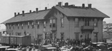
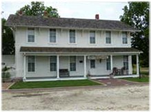
William Barstow Strong guided the Santa Fe Railway through an era of expansion that by 1881 included 7000 miles of track. Fred Harvey knew William Strong and entered into an agreement to purchase the Clifton House in Florence Kansas in 1878. This became the first Harvey House and was of importance in the growth and uniformity of the Harvey House concept.
Fred Harvey made extensive use of the telegraph to further his business. Orders were placed with suppliers by wire. An important advancement was the passenger meal ordering in route. In this fashion the meals could be prepared in advance, allowing service on arrival at Harvey House. Thus, the station stop could be limited to 30 minutes. In an effort at continuous improvement, Fred Harvey kept a diary of thoughts, and he scribbled in the diary daily.
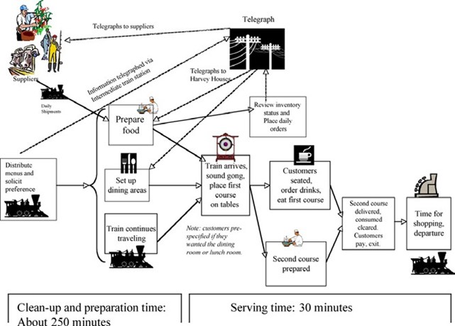
There were a number of principles for the Harvey chain:
- Standardization and sanitation were key to the operation.
- With the assistance of the Santa Fe Railway, a special box car shuttled twice weekly between Los Angeles and Kansas City. This car carried fruits and vegetables from California and on return carried Kansas City meats.
- A standard bill of fare was prepared in Kansas City and distributed throughout the operation. This was to ensure the method of food procurement that passengers did not receive duplicate meals on their journey.
- Food procurement was without compare.
- Coffee was a special blend for uniformity.
- Milk, butter, and eggs came from Harvey farms.
- Managers could make local vegetable purchases.
All of this came at a cost to Fred Harvey’s health. He was diagnosed with “Americanitis”. Today this is termed nervous exhaustion. He suffered from chronic ailments since having typhoid fever. Sanitation was a concern of the Fred Harvey chain, and this gave rise to pasteurization of milk and the individual single serve bottles. Fred Harvey was not one to let a marketing opportunity go by and his bottles had Fred Harvey on the bottle and cap.
His business was greatly improved with the addition of David Benjamin as the general manager, and Tom Gabel as the manager of the Raton New Mexico Harvey House. To build on the success of the chain, Fred Harvey recruited the nation’s first workforce of women, the Harvey Girls.
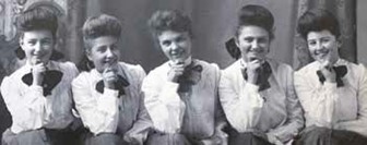
These women were recruited by newspaper ads from the east and Midwest to work as servers in the Harvey Houses. They were from 18 to 30 years of age, and agreed to a year long contract of employment. The initial pay was $17.50 per month plus tips. They were supplied with room and board, and uniforms. During working hours, which were 10-12 hours per 6 or 7 day weeks, they were required to have their hair pulled back and tied with a white ribbon. The contract stipulated that if they left prior to the end of the contract they were to forfeit one-half their pay. Even with that, the number one reason for leaving was marriage. It is said that Fred Harvey tamed the southeast with this labor force. These were educated women and added sophistication to the Harvey House. They were trained in Kansas City for 4 to 6 weeks and then assigned their permanent location. The training included how to carry a tray of food, when to serve drinks, and serving side. Many of the rules are in place today at dining establishments.
This is an amazing addition to the southwest. Imagine the mad rush at the arrival of a passenger train with hours of slack work between meals. Coffee was important for the Harvey House. They had a special coffee blend prepared in a large Zahner coffee pot in 4, 6, or 8 gallons of coffee. The coffee was kept for 2 hours and then discarded, so you always got fresh coffee at the Harvey House.
The first health resort was developed at Las Vegas, New Mexico with the Montezuma Hotel and Hot Springs. Fred Harvey was tasked with overseeing the construction of the hotel, and he returned to later manage the establishment. The hotel continues today as a college administration building.
The Fred Harvey Company was in the short list to provide catering for the Columbia Exposition in Chicago 1893. Luckily for Fred Harvey, they lost the contract to a New York firm. The Panic of 1893 bankrupted over 100 railroads including the Santa Fe Railway. Fred Harvey company survived and was able to renegotiate the contract with the new Santa Fe Railway. In 1888, Fred Harvey was providing service on the Santa Fe dining cars and again a re-structured railroad gave the dining car service to Fred Harvey in 1895. Ed Ripley was the ATSF president after 1895 and he urged Fred Harvey to retire and leave the company in the hands of the “boys”. This ushered in the era of Ford Harvey and an expansion of the business. In keeping with the cooperation with the railroad, news stands were added to the operation. In that fashion, travelers could get a local home newspaper while on their travels. Fred Harvey ran the restaurants in Kansas City Union Station, Los Angeles Union Station, and Chicago Union Station.
Ed Ripley had a vision for hotels along the Santa Fe Railway in the Mission style. The first of these was La Castenada in Las Vegas. This was completed in 1899 and hosted the Teddy Roosevelt “Rough Riders”. The hotel was closed in 1948 but reopened in 2019. It is operating as a hotel, dining room, and saloon. Nearby the Harvey House Girls dormitory is open as a museum showing how the workers lived.
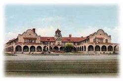
In a more somber note, Fred Harvey was diagnosed with colon cancer in 1899 and after surgery in England, he returned to Los Angeles. He soon returned to Kansas and died in 1901. The company continued to operate as Fred Harvey. Travelers were told that they were served by Fred Harvey not by a company. The company was run by Ford Harvey in allegiance with John Huckle, and the 10th Legion. 1901 was momentous as this is when Ed Ripley took a contingent to the Grand Canyon along with Ford Harvey. Ford was taken by the grandeur, and he lobbied to have the canyon as a National Park. The travelers met with Charles Fletcher Lummis and later with Richard Weatherill, both of which spoke of the ancient Indian culture.
In parallel with the interest in the Grand Canyon and the Indian culture, Hermann Schweizer became the buyer for the company of Indian blankets, pottery, and jewelry. He roamed the area around Ganado, Arizona, visiting trading posts to acquire the pieces. The practice was twofold. He found items of significance to add to the Fred Harvey museum displays, and to source items to sell in the Harvey Houses. He was quite successful and was attuned to the customer’s wants. John and Minnie Harvey Huckel were Hermann’s bosses, and the pair were in charge of the Fred Harvey newsstands. The three were successful in establishing the Indian Department of Fred Harvey. They amassed a guide for Native American symbols for the tourists. The thunderbird symbol was a widely recognized symbol of the southwest elements of jewelry, and it was included in many of Fred Harvey designs.
Coincident with the Native American fascination of the company, Fred Harvey hired Mary Colter as an Architect and designer in 1910. She was unique in that she was focused on earlier Arts and Crafts style as the profession was moving toward Art Deco. She was strong willed and able to thrive in the “man’s world” of architecture and construction.
The folowing is a list of projects undertaken by Mary Colter:
- Decorated the Indian Building at Alvarado 1902
- Hopi House, Grand Canyon 1905
- El Tovar Cocktail Lounge 1905
- El Ortiz, Lamy, NM 1910
- Union Station, Kansas City 1913
- Lookout (Studio), Grand Canyon 1914
- Hermit’s Rest, Grand Canyon 1914
- Painted Desert Exhibit, San Diego, Panama Exhibition 1915-16
- Phantom Ranch, Grand Canyon 1922
- El Navajo, Gallup, NM 1923
- Union Station, Chicago 1925
- La Fonda, Santa Fe, NM 1929
- La Posada, Winslow, AZ 1930
- Watchtower, Grand Canyon 1933
- Bright Angel Lodge, Grand Canyon 1935
- Victor Hall, Grand Canyon 1936
- Mimbreño Pottery, sold at El Tovar 1936
- Colter Hall, Grand Canyon 1937
- Union Station, Kansas City, 1937
- Union Station, St. Louis 1937
- Union Station, Los Angeles 1939
- La Costina Cantina in Alvarado, ABQ, NM 1940
- Decorated Painted Desert Inn, Petrified National Park 1947
- La Cantinita at La Fonda, Santa Fe, NM 1949
It is interesting to note the number of structures within Grand Canyon National Park. She became good friends with Hermann Schweizer and the pair explored the area extensively for inspiration.
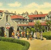
To establish validity to the Indian Museum at the Alvarado, Doctor George Dorsey, curator of the Field Museum in Chicago moved into the Alvarado Hotel and oversaw the Fred Harvey Indian Department. He was the first of many academics visiting the museum and the collection. Elle of Ganado, a Navaho, was the weaver of many of the blankets for the company and she was described as the finest weaver of blankets. In 1903, she was chosen to weave a copy of the honorary membership card for President Theodore Roosevelt to the Commercial Club of Albuquerque.
Mary Colter’s work defines the now accepted Southwestern Design Style. This is characterized by plaster walls, exposed wood and stone, accented by turquoise elements. This was popularized by the use along the Santa Fe Railway.
Many of the projects have be torn down as railroad travel lost its luster and the company changed. La Postada was privately restored and continues as a hotel and dining room in Winslow Arizona. It is a grand place with enduring elements of Mary Colter’s design and the Fred Harvey operations.
Ford Harvey was lobbying for Grand Canyon National Park from 1901 to 1919. It was designated a national park in 1919. This spurred another spurt in building at the Park. Ford Harvey developed a lesser resort at the rim to accommodate all classes of people wishing to visit the national parks. In part this lobbying for the designation was so that Fred harvey could negotiate with the National Park Service for the exclusive rights to provide lodging and services at the national parks.
The El Tovar hotel opened in 1902 with a Mary Colter designed cocktail lounge. The hotel was designed by Chicago Architect Charles Whittelsey to evock elements of a swiss chalet and a norwegian villa. Natural materials were used in construction and it was not entirely foreign to the environment. Adjacent to this hotel, Mary Colter designed the Hopi House opened in 1904. This was another Indian Building for Fred Harvey. The structure is significant as it was the first Mary Colter building for Fred Harvey and influenced the collaboration with the National Park Service. West of El Tovar, the Lookout Studio was constructed with a Mary Colter design. This was a studio space where visitors could photograph the canyon, view the canyon through telescopes, or quietly contemplate the beauty of the canyon.

The flurry of Fred Harvey activity at the Grand Canyon did not go un-noticed by competitors. The Kolb brothers set up a studio at the Bright Angel Trailhead and offered photo books for sale. Fred Harvey countered with their own books for sale. The brothers made a movie of the trip down the Colorado River and showed that daily from 1915 to 1976.
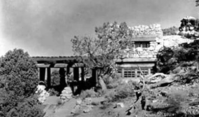
The company wanted a rest stop at the west end of West Rim Drive. Mary Colter designed Hermit’s Rest to appear as a aged structure made of local materials. In the true National Park Rustic style, the materials were hand hewn and aged with soot and cobwebs to represent an old structure made by the Hermit himself.
The Watchtower at Desert View was designed to represent an ancient kiva and watchtowers found at the ancient peoples’ ruins. The interior was decorated with murals of Indian life and beliefs. Fred Kabotie, Hopi artist, painted murals in the Watchtower. He later managed the gift shop at that location.
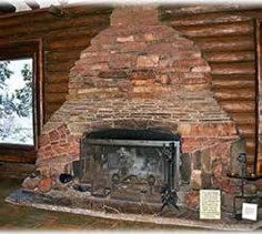
As directed by the Santa Fe Railway, Mary Colter designed the Bright Angel Lodge. This was to be moderate priced lodging for canyon visitors. The geologic fireplace within the lodge is a replica of the canyon walls using stone from the layers. The lodge opened in 1935.
The Phantom Canyon Ranch was a lodge at the bottom of the canyon along the Colorado River. These were separate cabins with a central canteen for provisions. The route to the Ranch was perilous crossing the Colorado on a wooden suspension bridge. There is a reason that only 1% of the canyon visitors spend a night below the canyon rim.
In keeping with the original concept of Fred Harvey, lodges and dining halls were spaced along the Santa Fe routes. These were largely in the adobe style architecture and featured Native American art and decoration.
Fred Harvey created many curios and souvenirs of the Santa Fe route and sold these in the shops and at newstands. One of the books published was “Indian and Mexican Arts” which promoted travel to the Southwest and included colorized photos from other artists.
Fred Harvey purchased an automobile tour operation that focused on driving the primative roads to remote sites. The drivers were responsible for the cars and couriers, or guides, were responsible for the guests. This was a rough riding outfit. It was not financially successful. Erna Ferguson was involved in the company and provided a wealth of knowledge. Under her direction, the couriers were trained to guide and inform the guests.
The San Francisco and San Diego Exhibitions in 1915 spurred an increase in travel to the coast. This led the travelers through the Indian lands of the Southwest and promoted more visits to the area.
Tragedy struck the Harvey Company in 1926 and 1928. Judy Harvey died in 1926. Ford Harvey died in 1928. The Fred Harvey company at the time of Ford’s death included 25 hotels, 40 sit down restaurents, 54 lunchrooms, 80 newstands, luxury hotels at Grand Canyon & Santa Fe, and running all consessions at seven major Union Stations.
Byron Schermerhorn Harvey was named President of Fred Harvey. This was a figure head position as Fred Harvey’s trusted associates kept the company running. Freddy Harvey, Ford’s son, was to assume the leadership role. He was interested in flight and had put together a cross country combined trip of air flights and train travel.
The depression hit Santa Fe Railway hard with a dramatic dive in revenues. Smaller eating houses were shut down. The Indian Detours was sold at a loss. La Fonda was retained and the Watchtower was completed. Harvey Houses assumed a new role during this Depression. They dispensed meals to drifters and struggling locals. The family went through growing pains, and changes to the operations were made and more were contemplated. In 1936, Freddy and Lucy were killed in a plane crash.
This threw the organization into turmoil. Ford’s daugther, Kitty, wanted to control the company. Bryon Harvey, Fred’s son, was against this as the company was never to be operated by a woman. Bryon prevailed and Kitty received a good deal of money for her stock.
MGM wanted a movie about the Harvey Girls and pushed Bennet Cerf into having a book written. This was turned into a screen play. The book was published in 1942. Fred Harvey company was pushed into the war effort setting up 8 large sandwich making operations. This was promoted by advertising that noted “K.P.- not for Private Pringle”. Servicemen were fed at the Union Station locations in their transit across the country.
La Fonda participated in the Manhattan Project as the office was located one block from the hotel. The Oppenheimer family stayed at La Fonda and many servicemen were moved through the area.
“The Harvey Girls” movie premiered in 1946, starring Judy Garland. Bryon Harvey Sr. died in 1954. The sons made a good attempt at reviving the company. They had rest stops on overpasses on the Illinois Tollway.
In 1966, the remains of the Fred Harvey company were sold to Amfac. In 1971, the remaining passenger service was surrendered to AMTRAK. This ended the partnership of the company and the Santa Fe.
Fred Harvey Company was a division of Amfac tasked with running the parks and resorts. Amfac was sold several times until in 2008, when it became a part of the Anschutz companies operating as Xanterra. Locations include Glacier NP, Yellowstone NP, Grand Canyon NP, and Mount Rushmore NP.
There is a weekend of Fred Harvey History: Fred Harvey History Weekend 2024, October 25 – 28, at New Mexico History Museum, Santa Fe, NM. More details can be found at: https://www.nmhistorymuseum.org/event/details/6000/15th-annual-fred-harvey-history-weekend.
June Clinic – June 17, 2024
Clinic – Colorado’s Narrow-Gauge Railroads – A Synopsis
Tom Brunner Biography
Tom was born, raised, and educated in Southern California. After graduation from the College of Engineering at UCLA, he was hired by the Federal Systems Division of IBM to work on government projects. This began a 35-year career in developing computer software, which evolved from writing code, analyzing software performance, designing programs, estimating work efforts for tasks, and writing requirements for new projects. Since IBM also means “I’ve been moved”, he spent from 2 months to 14 years in a variety of places: Pasadena, CA and Houston, TX on NASA projects, north of Philadelphia, PA on a Navy project, and Seattle, WA, Thousand Oaks, CA, and Boulder, CO on Air Force projects. Tom and his wife have two children and six grandchildren. He enjoys visiting historic sites – buildings for his wife and trains for him. He has been volunteering at the Colorado RR Museum for over 20 years.
Colorado has an interesting and expansive railroad heritage – and much of it started as a narrow gauge. Two original segments, as well as one recreation, today exist as tourist railroads. Also, several museums and smaller displays contain significant artifacts of this history. If you do research and know where to look, many other remnants can also be found. Tom’s presentation will begin with a little history of several of these narrow-gauge lines, but the major portion will be pictures he has taken over the last 50 years of what can be seen in museums, displays, and “off the side of a side road”.
Tom Brunner gave us an overview of Colorado’s Narrow Gauge Railroads. He is an author of books on the Rio Grande Narrow Gauge and has assembled a collection of photographs showing the narrow gauge railroads in Colorado. Colorado felt ignored by the transcontinental route through Wyoming. So, in response, they constructed a railroad north to Cheyenne. Golden wanted in on the action and built a line from Golden into Denver. The Kansas Pacific Railroad was built from Kansas to Denver. This meant that connections from Denver to the east, north and a short line to the west was in place. These connections were all standard gauge railroads. The Denver and Rio Grande started to build a narrow gauge line south from Denver in 1871. The goal was to reach Mexico. The line diverted itself west to take advantage of the mineral fields in Colorado. The result of all this wandering left a narrow gauge circle in Colorado. The map shows the extent of the narrow gauge lines in Colorado and northern New Mexico.
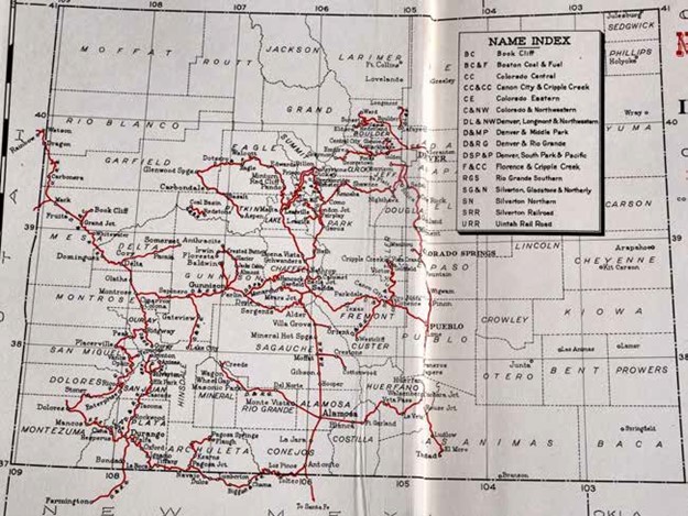
Basically, the Rio Grande and Santa Fe railroads were in competition for the route west from Pueblo through the Royal Gorge and south from Trinidad over Raton Pass. The Rio Grande was not successful in either of the routes until a series of court challenges and weird trackage rights agreements resulted in the Rio Grande locked out of the southern route into New Mexico and the Santa Fe losing the Royal Gorge to the Rio Grande. The Rio Grande built miles of track into the mountains and western Colorado. This opened a large number of scenic passenger locations and gave them access to the rich mineral areas. Tom gave an interesting set of facts on each of the narrow-gauge railroads.
The pictorial review of the Rio Grande’s 3rd Division allows us to see scenes from Salida, Mears Junction, Marshall Pass, Sargents, Gunnison, Cimarron, Cerro Slide, Montrose, Monarch, Round Hill, Crested Butte, Lake City; and Ridgway. A few of the photos by the presenter are shown here.
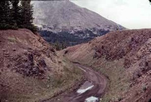
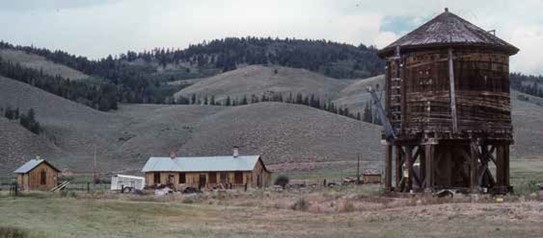
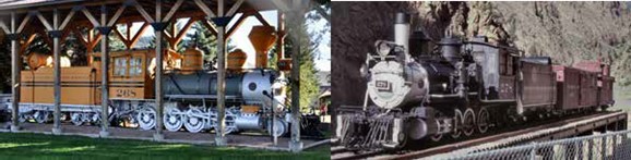
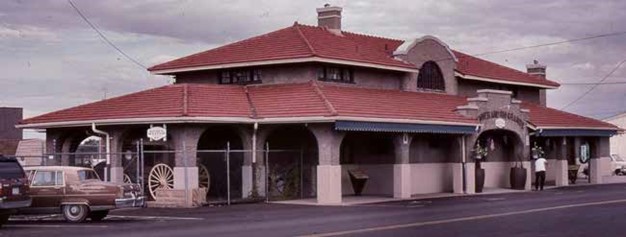
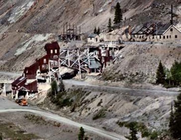
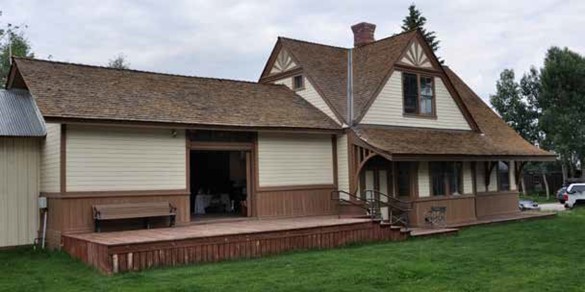
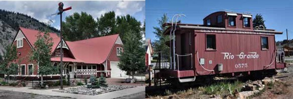
It is great to see that many of the railway structures have been re-purposed to serve the community. The locomotives, and rolling stock being displayed in the community is a tribute to the railroad legacy for these communities.
A smaller Narrow-Gauge Circle was found in the Rio Grande Southern routes. These are Ridgway, Placerville, Vance Junction, Telluride, Trout Lake, Rico, Dolores, and the East Mancos Tank.
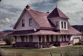
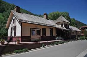
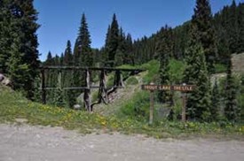
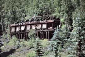
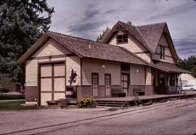
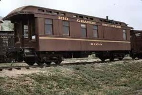
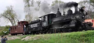
Again, it is great to see the level of preservation of the Rio Grande Southern structures and equipment.
Another Narrow-Gauge Circle was made by the Denver and Rio Grande in its 4th Division. These locations include Durango, Bondad, Piedra River, Arboles, Pagosa Junction, Navajo, Antonito, Embudo, Santa Fe, La Jara; and Alamosa.
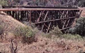
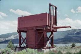
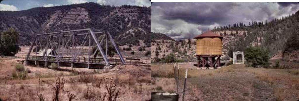
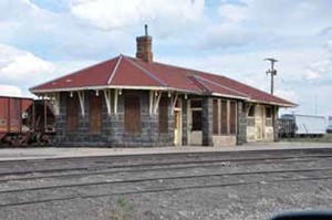
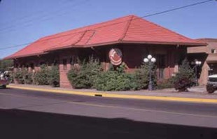
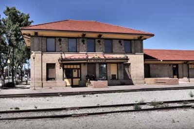
The presentation progressed with the routing of the narrow gauge Colorado and Southern. The highlighted locations included Central City, Idaho Springs, Georgetown Loop; and Silver Plume. These locations were part of the Colorado Central Railroad which operated to the east of Golden and west into the Clear Creek Canyon area. With the elevation changes in this area, creative railroad engineering was called into play.
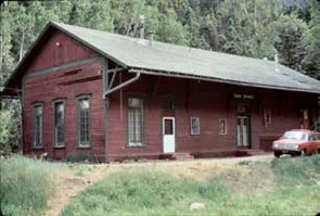
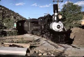
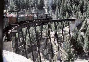
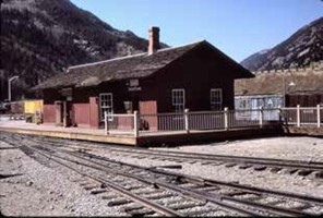
The Colorado and Southern also built south from Denver and into South Park. The notable locations on this line were Kenosha Pass, Jefferson, Colorado Midland Crossing, Como, Boreas Pass, Baker Tank, Breckenridge, Leadville, Alpine Tunnel, and Pitkin.
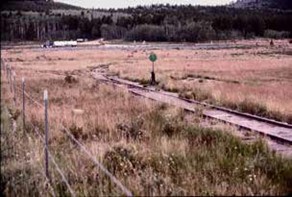
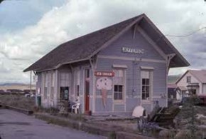
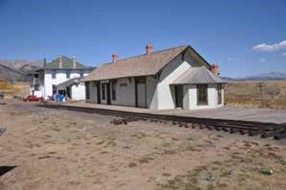
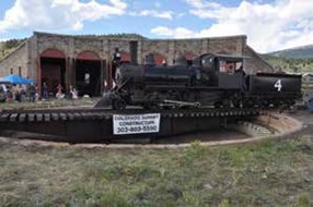
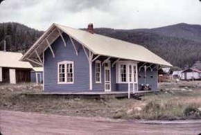
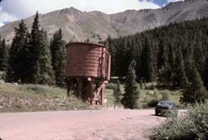
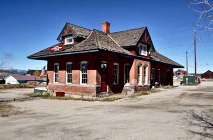
A number of locomotives and rolling stock have been saved by the Colorado Railroad Museum and are on display on the grounds.
Other narrow gauge railroads were constructed in Colorado. These lines were very short in overall length and only lasted a short span of time. The Colorado and Northwestern pushed west from Boulder and into Ward and Eldora.
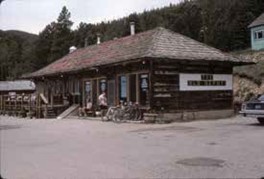
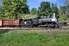
The Florence & Cripple Creek pushed north from Florence into Victor and Cripple Creek. This tied the mining district to Denver and Rio Grande railroad.
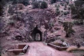
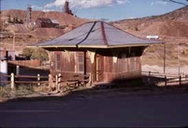
The Silverton and Silverton Northern radiated from Silverton to related mining camps falling short of the stated goals.
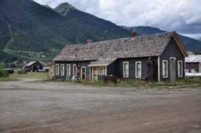
The Uintah Railroad moved north of Grand Junction through Mack and Carbonera before terminating at Watson and Rainbow in eastern Utah. Examples of the rolling stock have been preserved and can be found in Grand Junction.
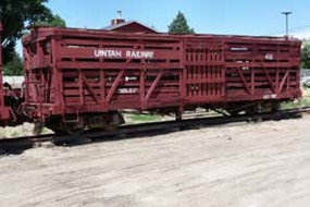
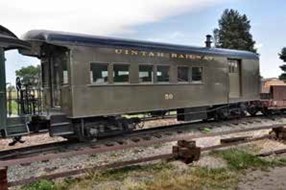
To conclude the clinic, we examined the survivors of the narrow gauge era in Colorado. The Denver and Rio Grande sold the Durango to Silverton route to the Durango and Silverton Narrow Gauge Railroad. The route follows the historic alignment of the track for the most part. The steam power has and is being converted to oil from the original coal fuel. They have added diesels to the fleet for those high fire danger times. The railroad provides tourist rides.
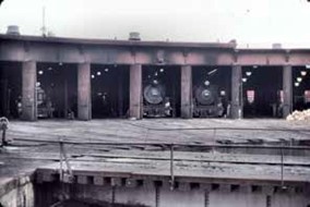
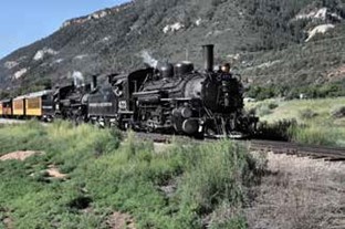
The other survivor is the Cumbres and Toltec Scenic Railroad. This is a joint venture between states of Colorado and New Mexico to retain the narrow gauge heritage in those states. The railroad runs between Chama, New Mexico, and Antonito, Colorado.
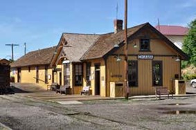
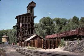
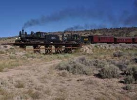
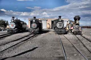
May Clinic – May 20, 2024
Clinic – How Geology Determined the Denver-Gunnison Mainline of the DSP&P
Steve Hart Biography
Steve Hart is a retired geological engineer who has been fascinated by trains since traveling in an M-K-T passenger train pulled by a steam locomotive at age 9. After a 42-year career, including consulting on remediation at dozens of mines, mills, smelters, and radioactive waste Superfund sites, he began giving presentations on mining history to local, state, and national historical organizations.
A group of businesspersons led by John Evans incorporated Denver, South Park & Pacific in October 1872. The objective of the line was to reach the San Juan mining region. The shortest route to the San Juans was via the South Platte River and extending the route through South Park, Trout Creek Pass, and Gunnison. Standing in the way of the railroad were four mountain ranges; Front Range, Mosquito Range, Sawatch Range, and the San Juan Range. In 1972, the known mining districts southwest of Denver included Breckenridge, California Gulch, and the San Juans. By using a diagonal southwest route, the railroad would be in proximity of the mining districts.
The cast of characters involved in the effort included John Evans. He was the second territorial governor of Colorado, who was fired after the Sand Creek Massacre. (It should be noted that during the incident at Sand Creek, he was in Washington, D.C.) He was President of Denver-Pacific Railroad tying Denver to the Union Pacific in Cheyenne. Founder of both Northwestern University in Evanston, Illinois, and University of Denver. President of Denver and New Orleans Railroad. He was a Colorado rancher, politician, developer, and promoter, but definitely not an Engineer. Leonard Eicholtz was a civil engineer and the only one of the professionals among the founders of the railroad. He was the Chief Railway Engineer, Union Army in Mississippi. He was employed as Construction Engineer for the Kansas-Pacific Railway, and the Union Pacific Bridge Engineer. He functioned as the Chief Engineer of the DSP&P from 1872 to 1882, and he surveyed the Georgetown Loop in 1881. Major James A. Evans was an English borne civil/railroad engineer in the UK and the US. He was the Union Pacific design and construction superintendent for the Laramie to Green River segment, 1863-1869. In 1878, he was named the Assistant Design Engineer for the DSP&P. In 1882, he replaced Mr. Eicholtz as the Chief Engineer for the remainder of the construction. He designed the east and west approaches to the Alpine Tunnel and the Breckenridge to Leadville High Line.
In 1872, there were a number of railroads In Colorado. These included the Denver- Pacific tying Denver to Cheyenne in 1870. The Kansas-Pacific later in 1870 tied Denver to Kansas City. Denver, South Park, and Pacific was incorporated in October 1872. Denver & Rio Grande constructed a water level route from Denver, through Colorado Springs, into Pueblo, and on to the Florence coal fields by November 1872. The Colorado Central Railroad had extended the line from Denver to Blackhawk by December 1872. The Panic of 1873 stopped all railroad construction in Colorado. This Panic was an economic depression that was widespread in Europe and North America. This was a strain on the banking systems brought on by a number of unfortunate events and worsened by governmental actions including silver demonetization.
The railroad was a three foot gauge rail line with the equipment chosen to be suited for mountain construction. This made the line less expensive to build and able to accommodate tight curves. The small equipment was less capable of handling the high grades that were a result of the route’s location.
The Denver, South Park, & Pacific Railroad routing on a diagonal line from Denver to Silverton cut across a number of physiographic features. The beginning in Denver is within the Denver Basin which is a sedimentary basin. In terms of this alignment an easy route to construct and maintain. The route then moves into the Front Range mountains. The route follows the South Platte River and further the North Fork of the South Platte River. This is canyon construction is in a narrow steep canyon demanding hard rock construction techniques. The route
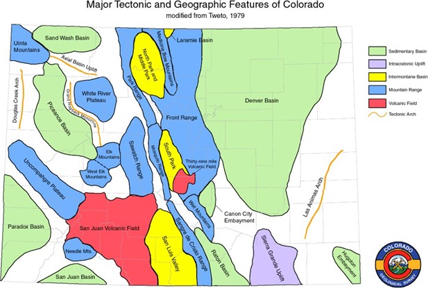
passes over Kenosha Pass into South Park. South Park is an intermontane basin with a few difficult geological features to the west edge of the basin. This kept the route south and east of Fairplay. Como was an important maintenance and crew point for the railroad with a stone roundhouse, depot, and crew quarters. The railroad then took on two mountain ranges in close proximity. The route entered the Mosquito Range at Trout Creek. Coming south into the Arkansas River valley, the railroad had a little respite from the mountain construction before pushing on into the Sawatch Range. This was the location of the Alpine Tunnel. This was a short-lived tunnel with a rather sharp curve within the tunnel.
The railroad pushed westward from the Alpine Tunnel and made its way into Gunnison. The railroad turned north at this point to Baldwin Station. This ended the railroad’s westward push.
The chosen route for the railroad intercepted a great number of geologic time periods and a variety of rock types. The rock types included igneous formations including granite, volcanic ash, rhyolite, and basaltic lava. The sedimentary rocks included sandstone, limestone, shale, and coal. The metamorphic rocks included slate, marble, gneiss, and schist.
The intrusive igneous rocks included formations from an igneous rock triangle diagram. These ranged from well cemented rock types to those of a rather loosely cemented nature. Those well cemented types were difficult to build on or through but provided long lasting stable slopes, cuts or tunnels. The loosely cemented materials offered easier construction but with the need for continued maintenance and were unsuitable for tunnel construction.
Central to Colorado geology is the Rio Grande Rift. This is a 29 million year old rift valley that extends from El Paso, Texas to Leadville, Colorado. The rift is interrupted at Poncha Pass by lava flows and east-west fault lines.
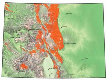
To get an illustration of the geologic obstacles, this map shows the extent of the pre- Cambrian Igneous and Metamorphic Rocks in Colorado west and south of Denver along the proposed rail line route. The contrast to the diagonal route of the DSP&P would be the Denver and Rio Grande route south of Denver to Pueblo and then west up the Arkansas River.
In an effort to illustrate the difficult materials, photos were shown of the pre-Cambrian metamorphic gneiss and schists in the South Platte Canyon with intrusions of pink pegmatite dikes. Farther west in the canyon, were the Pikes Peak granite domes.
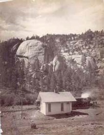
These features were of significance to rate naming the formation. This is dome rock and sphinx rock. Further along the alignment along the North Fork of the South Platte River, the railroad encountered fine grained schist which required blasting and coarser grained gneiss which was easier to cut near Shawnee, Colorado. This is located west of Bailey. In 1878, the sliver boom had begun in Colorado. At this point, Denver, South Park, and Pacific were constructed to the foot of Kenosha Pass at Webster. The Denver and Rio Grande Railroad was constructed to Canon City. Both of the railroads were a long way from Leadville. Construction over Kenosha Pass encountered Kenosha Granite. This is an older formation, and it was intruded by Pikes Peak Granite. This made for varied construction with dissimilar materials.
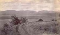
Kenosha Pass was finally summited 1880 and the railroad moved into South Park. The Como station, roundhouse, and crew facilities were constructed. Como was a division point for the railroad with lines proceeding north to Breckenridge over Boreas Pass. The line was constructed south along the east edge of Red Hill. This was a hogback type of formation of Dakota Sandstone. The railroad constructed a branch line from Garo’s to Fairplay and Alma. The Fairplay mining district
was largely a series of hydraulic mining operations following the South Platte River. These mining operations culminated in floating barge mining into the 1930’s. The spoils from the operations can still be seen today.
The railroad constructors continued into the Mosquito Range and pushed west up Trout Creek Pass. The geology in this area was lower Paleozoic rocks sitting on top of Mosquito Range pre-Cambrian granodiorite. The mining in the area was small vertical shaft mines.
This route led to the Rio Grande Rift and Buena Vista. The DSP&P moved into Buena Vista in March 1880. The D&RG arrived 3 months later.
At this point, we must compare the two railroads and the approach to Leadville.
DSP&P
- Blasted through gneiss and granite along South Platte and North Fork
- Crossed Front Range via Kenosha Pass @10,001’
- Through South Park @ 9,000’ on sediments
- Crossed Mosquito Range via Trout Creek Pass @ 9,500’ in granodiorite
- Buena Vista to Leadville on D&RG tracks: Joint Operating Agreement
D&RG
- Laid on Plum Creek alluvial terraces to Palmer Divide
- Crossed Palmer Divide @ 7,300’ on sedimentary rocks
- Followed sediments/terraces along Monument/Fountain Creek to Pueblo @ 4,700’
- Water-level route up Arkansas River thru Royal Gorge to 7,100’ Salida
- Salida to 10,200’ Leadville on alluvium at ~0.9% grade
A comparison on the routes, notes the DSP&P has a much higher elevation route. This leads to much more severe weather and extended shutdowns for snow removal and abatement.
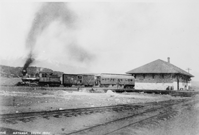
This is a DSP&P mixed train at Nathrop. This is the interchange between DSP&P and D&RG. Nathrop is about 8 miles south of Buena Vista. It is interesting to note the differing styles of railroad construction. The DSP&P is constructed on a substantial embankment, while the D&RG in the foreground gets by with minimal fill and ballast.
Forging westward from Nathrop, the railroad was set once again to cross the continental divide. This time the geology is Mount Princeton Batholith. This is a relatively young formation of Quartz monzonite deposited at a shallow depth. Quartz monzonite has approximately equal parts plagioclase and orthoclase feldspar, only 5-20% quartz. In comparison, granite has 20% to 60% quartz. The reading here is that it is not very competent. On June 2, 1879: Chief Engineer Eicholtz wrote of Altman/Alpine Pass route, “Do not regard this practical or safe at any reasonable cost.” At which point, Major Evans was appointed chief engineer and was tasked with building the Alpine Tunnel.
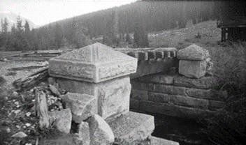
Along this route to the eastern tunnel approach, the rail line encountered Chalk Creek. This is not chalk at all but rather weathered, highly altered igneous granodiorite. Further west, the line passed St. Elmo, a small silver-lead mining district which persisted from 1870 to 1940. The railroad crossed a creek at Hancock with an elaborate structure. It is important to remember here that the chief engineer had been replaced, so it was important for the new leadership to put their stamp on the railroad.
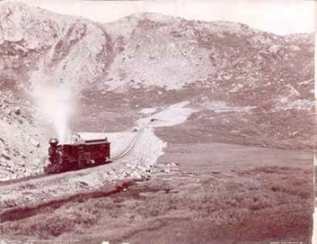
Finally, we get to the Alpine Tunnel. This cost $300,000 dollars to complete and at least one documented worker fatality. The tunnel could be termed a “White Elephant” or more properly a “Money-Pit”. The East-West approach grades were 3.26% – 4%. The tunnel length = 1,810’ with 160’, 24o curve inside east portal. The tunnel was constructed through Quartz monzonite that was so weak, that the entire tunnel was supported by imported redwood posts, beams, and lagging at great cost. The first train transited the tunnel in July 1882.
By this time, the Denver and Rio Grande had reached the center of the San Juan mining district on a route that crossed 9,400’ LaVeta Pass, through the 7,500’ San Luis Valley, across the 10,000’ Cumbres Pass, and into 6,500’ Durango.
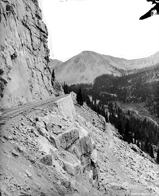
The west approach to the Alpine Tunnel passes the most famous geology on along the DSP&P. The Palisades were formed by erosion of the vertically jointed, quartz monzonite of the Tertiary-age Mt. Princeton Batholith. Continuing west the railroad passed through the Pitkin mining district. This was a small mining area. The DSP&P met up with the D&RG at Parlin. This is in the Tomichi Creek valley where Gunnison is located. This is the termination of the mainline of the Denver, South Park & Pacific. A branch line continues north to Baldwin which was a coal mining district. Overall, the South Park line was a more scenic adventure into western Colorado. It was a tourist line in part that was trying to service the mining districts of Colorado. The routing of the line kept the major mining districts of Colorado at some length. This can be illustrated by a comparison of the yields of the various mining districts:
DSP&P
- Fairplay/Alma ($44)
- Chalk Creek ($22)
- Pitkin/Qtz Creek ($10)
- * Leadville ($462)
- * Breckenridge ($55)
- * Kokomo ($13)
- * Climax ($315, 1918) * On new “High Line”
D&RG
- Silverton ($117)
- Ouray ($86)
- Crested Butte (coal = $22)
- Leadville ($462)
- Aspen (1886-92 = $112)
- Lake City ($25)
- Creede ($50 after 1890)
- Cripple Creek ($455) (via Florence &Cripple Creek Railroad, from 1894-1912)
Denver, South Park, & Pacific lost to Denver and Rio Grande due to a number of factors. The principal reason was the geology of the single-minded quest of a direct route to a precious metal bearing area. The chart above shows that this was mis-guided as the Silverton mining area was not that outstanding among the Colorado mineral fields. The directed route pushed the railroad through three mountain ranges. The route was filled with crystalline rocks that required blasting. This activity cost $4,853,000 and resulted in a route that bypassed most of the metal mining districts. The Alpine Tunnel was another misstep in routing the railroad. The tunneled material was not competent and resulted in delays and the additional cost for shoring and bracing. Ultimately, this system failed. The route had no major coal mines which required costly and time- delaying uphill hauling of fuel. The route was a high elevation rail line with the need for costly snow removal or delays due to the lines condition.
An aside to the pursuit of precious metals is the profitable Morrison branch of the railroad. This branch was located just south of Denver and accessed a mixed freight area with passenger service. The railroad was able to carry cut sandstone, aggregate, coal, and lumber. This lesson on railroad viability was lost on the management in the single minded pursuit of glittering metal.
The railroad continued operations in the South Platte Canyon until 1937. At that point in time, the canyon was surrendered to Denver Water.
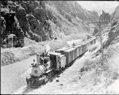
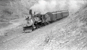
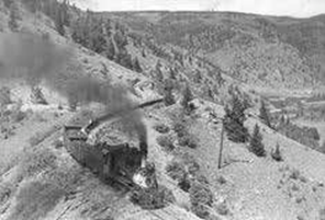
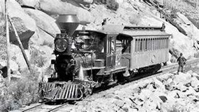
NOTE: Photo/map credits: Denver Public Library and Colorado Geological Survey
April Clinic – April 15, 2024
Clinic – Backdrops: How to Paint and Blend with Mid and Foreground
Mark Shifter Biography

Mark Shifter is a person with Midwestern roots and Front Range experience. Born in the St. Louis area, raised in Missouri, Iowa and Nebraska, Mark received a Bachelor’s and Master’s Degrees from the University of Nebraska-Lincoln in the mid-80’s. He spent 13 years in the Kansas City area before relocating to Colorado 23 years ago. Mark has been a licensed architect since 1991 and has his own practice designing residential and commercial projects. While architecture is a passion and his livelihood; he is also a musician and songwriter and dabbles as an artist as well.
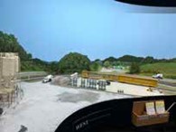
Mark Shifter has been painting backdrops in this fashion for about 17 years. Mark will use a PowerPoint presentation to step through his process. He utilizes three levels of finish that he will discuss, with photo examples of each level. He will illustrate the paint and brushes he uses, and then he will give a live demo on how he creates his backdrops.
Mark Shifter, modeler of the Franklin Southern Murphy Subdivision, presented a clinic on “How to Paint Backdrops and Blend with the Mid and Foreground”. Mark started the clinic with an overview of his journey as an artist. He is a practicing Architect, where his work is connecting the constructed world to the people using it. He also painted some mixed media artwork that is on display within his home and the entry of the layout area. His most ambitious effort to date is the painting of the backdrop scenes on the Franklin Southern Railway. This is a large discontinuous art project, over 120 feet in length, using mixed photo backdrops and painted scenes to blend the countryside to match and complement the true actors on the stage, the model trains.
Photo backdrops are useful for modeling. They offer highly realistic scenes using commercial backdrops or created from your photographs. Utilizing editing software, the scenes can be blended end to end for a continuous photo scene.
The drawbacks to the photo backdrops are the cost for large layouts, the learning curve for editing software can be steep, and the installation is challenging due to the length of the photos and matching lines for concurrent scenes.
On the other hand, painted backdrops are completely flexible with custom scenes and a high level of specific detail. The cost of the materials for the painted backdrop is relatively low, but the true cost is in the time required to envision and execute the painting. As with most modeling efforts, the results may not meet your expectations without a great amount of practice.
Utilizing painted backdrops in combination with the photo elements, the perspective can be adjusted to suit the viewers. This allows one to be transported to western North Carolina within the Smoky Mountains. Mark was able to create accurate depictions of his chosen layout design elements around the layout. Mark was inspired by several artists and modelers in his efforts. These include James Michael Smith, a YouTuber; Mike Danneman, a published artist and N scale modeler; and Tom Johnson, a model railroader and artist. They all create scenes to transport the viewer to the locale within the chosen perspective.
The materials that are used for the painted art are:
- Craft acrylics
- Tube acrylics
- Latex paint for blocking
- Oil paints
- An assortment of brushes, generally a less expensive variety
- Colored pencils, used for highlights of tree branches, pavement, curbs, sidewalks.
The chosen or mixed colors are to match or mimic the scenery materials used. The ground cover, trees, and shrubs are mated to the paint colors. Paving colors are carefully matched to the adjacent scenery material color for a seamless match at the intersection.
The scenes are blocked generating the basic shapes and flow of the landforms. This gives the start of the backdrop and allows for visualization of the land shapes and reference between the foreground and background relationships. These are latex or acrylic paints that will be covered by future painting.
At this point in the process the paint colors are mixed to match scenery foliage. The tree canopies are painted forming tree shapes in the canopy. To add depth and realism to the scene the colors are varied to provide contrast and definition from the light to dark areas.
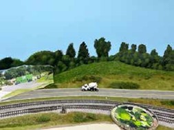
The final details are added to the scene with lighter contrasting color blends to better define the canopies and add in more defined foliage.
A surprising element of blending the photographic and painted elements is the brightness of the photo colors. To assist in matching up the color palette, it is suggested you experiment off the layout with the colors and photos to obtain a critical color match. In blending the elements of the backdrop, it is a good practice to use trees and shrubs to hide the seams and transitions.
Mark shared a number of scenes from his layout to illustrate the successful use of these techniques.


Scenes from the papermill area on the layout. Note the background mountains in blue tones with the foreground hills in the green tree canopy colors.
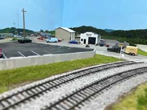
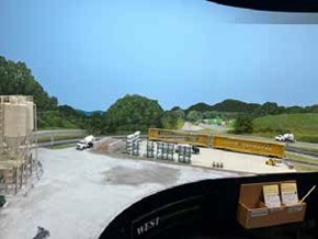
From above, the left photo shows a painted background scene with the parking area as a photo insert. The chain link fencing was added to the scene using Prismacolor color pencils. These are useful for blending colors and there are a variety of colors from which to choose.
The right photo shows Photoshopping the road on the backdrop can be modified to a differing alignment adding depth to the scene.
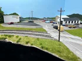

The left photo shows the use of a photo only backdrop. This is a photo of Franklin which is situated outside of the Smoky Mountains and offers more open terrain. The right photo illustrates Mark’s technique to add build flats to the scene. The photos of buildings were sized in photoshop to give a 7-foot-high model door height. The buildings were blended together in a reasonable order to provide the building backdrop in front of the painted trees and hills behind. The building photos were mounted on a cardboard backing.
As a finale to the presentation, Mark demonstrated his painting techniques. The acrylic paints used can be blended to make matching colors to the photos or to the existing painted scenes on the layout. He modifies the photos to remove unwanted elements like phone, power or fence lines.

This is the basic blocking on the painting/ backdrop. The shapes are roughed in using base colors. The base of the painting has the beginnings of a roadway. This is 24 scale feet wide. The roadway will curve off into the distance as the painting progresses. Using the dark acrylic paints the tree canopy is added to the scene with a stippling motion. Build up the colors, going to lighter shades in this case, use cadmium yellow.
The color guide is the scenery materials. This is a guide to reproduce the colors from scene to scene and session to session. He uses inexpensive brushes so that you can replace them as necessary. There was a good deal of discussion on the brushes and paints. The key to the technique is the laying of the colors to differentiate the tree foliage and the grass ground cover. The road was added to the painting at the lower edge curving into the background. Road striping was added to the road with colored pencils. The road shoulders were modeled with colored pencils to replicate the gravel. Pencils were also used to add in branches to some of the foreground trees. This is a tremendous set of skills to add to your modeling.

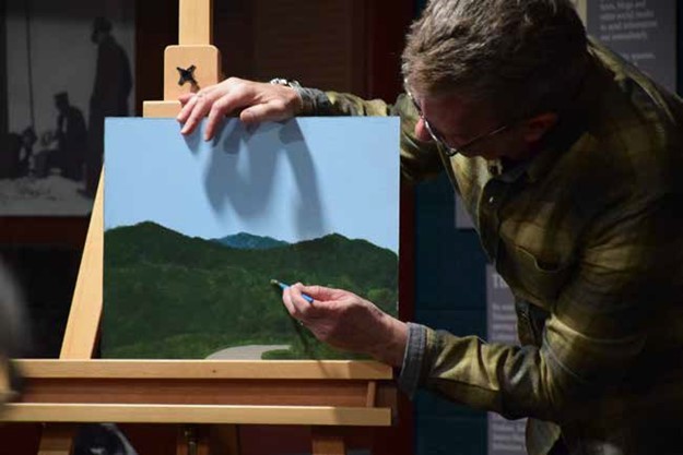
As with all techniques, practice is the key. Remember if you don’t like the result just paint over it and try, try again.
March Clinic – March 18, 2024
Clinic – The Oregon, California and Eastern Comes Alive at the Colorado Model Railroad Museum
Bill Kepner Biography

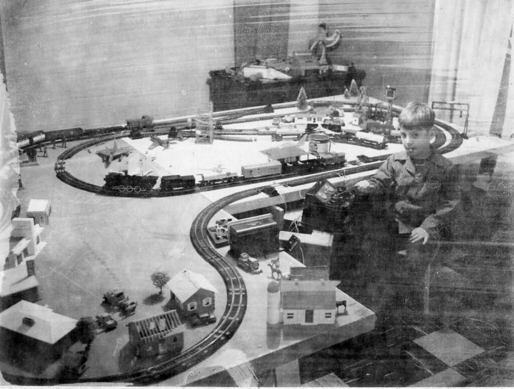
Bill grew up on the east coast, migrated west for college and a career, and ended up in Fort Collins where he worked as a Software Engineer for many years. Has a great wife, Cindy, and two adult children, one of which is a locomotive mechanic for a regional railroad in South Dakota. Non-railroad hobbies include photography and Arduinos. He has been the Director of Operations at the Colorado Model Railroad Museum since November 2023, where he tries to keep things fun for CMRM guests and volunteers.
This is an HO scale model railroad housed in the Colorado Model Railroad Museum in Greeley, Colorado. The railroad occupies around 5,500 square feet of the 10,000 square foot museum space. The museum and railroad are an outgrowth of David G. Trussell’s love of trains and model railroading. Mr. Trussell spent a great deal of time in Oregon and was enchanted by the logging railroads of the area. He was active in modular railroading in Oregon and after moving to Colorado continued those efforts. The modular group he was a part of developed a 64 foot by 64 foot modular layout that was set up at numerous train shows.
Mr. Trussell was always doodling railroad plans and based this interest, on a May 1951 article in Model Railroader by Linn Westcott, “If I had a Million Dollars”. The article named a number of elements for this fabulous model railroad; high ceilings, few windows, easy entry way, lobes or peninsulas, yards at each end, spotlights highlighting the elements, a balcony for viewing, CTC machine for routing control, and mountains at eye level. Since this was 1951, the article did not anticipate DCC control or mechanical improvements to the trackwork and rolling stock.
He retired and wanted to give back to the community. His original idea was to construct a model railroad as a park or museum in the community with the city assuming responsibility. The City of Greeley was not convinced it should be a participant and declined the idea. At that point, the Colorado Model Railroad Museum became a 501 (c )3 nonprofit with an independent board of directors. The museum opened for public visitation in 2009.
The model railroad was constructed using well defined standards and practices to maintain the integrity of the railroad and withstand the rigors of public use. The trackwork was executed to be faultless, with the only track caused derailments to be a faulty turnout.

History of the OC&E
- 1909 – Southern Pacific arrives in Klamath Falls.
- 1917 – Ground broken for Klamath Falls Municipal Railway.
- 1922 – Track completed to Sprague River.
- 1927 – Southern Pacific buys the line.
- 1933 – SP and Great Northern begin joint operations.
- 1975 – Weyerhaeuser buys the railroad.
- 1991 – Abandonment approved.
- Right-of-Way acquired by Oregon State Parks.
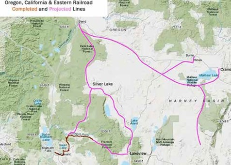

Lakeview Oregon was the terminus of the Oregon, California and Eastern Railroad. The depot was purchased by Mr. Trussell. The line was abandoned by Weyerhaeuser in 1991. The line exists in part as a biking and hiking trail by the Oregon State Parks, as the OC and E Woods Line State Trail. The model railroad captures the look and feel of the rugged terrain and the surrounding area with the backdrops and the on line topography. The route tied to an extensive and changing logging railroad network in the mountains north of the railroad and west of Summer Lake in southern Oregon.
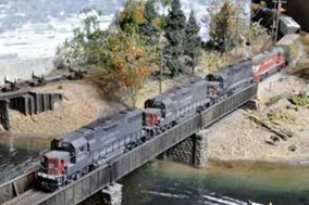
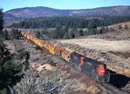
The route was operated by Southern Pacific and the Great Northern on a 5 year alternating basis. The maintenance on the line was deferred in the hopes the next operator would shoulder the capital expense. This ultimately led to Weyerhaeuser purchasing the line and operating the final stages of its existence. The line tries to run prototypical engines and equipment. There is a logging turn that runs from Klamath Falls to the logging loadout on the hill and returns. There is an opportunity to run logging equipment with geared locomotives and long strings of skeleton cars of logs.
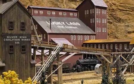
Mining interests are represented on the railroad with Lucky Lass Mine Company, which is a stretch on the prototypical line. The line is populated with HO figures in action along the line. There is a switch job to switch the logs into the mill pond. To add to the action, a local passenger train is run along the line for the hunters, hikers, and fishermen to points along the grade. The line extends to a port where ships are loaded with lumber. The ship models were intended to be floated in water, but with the passage of time, it was determined that they should be fixed.
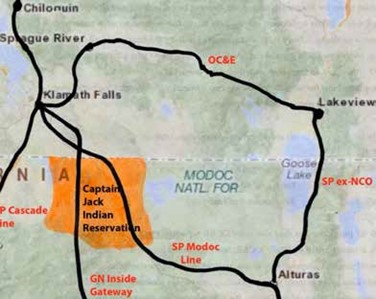
In an effort to make the line handle more mainline traffic, the Indian Reservation on the mainlines in the area were set to charge a car fee within their lands. This meant that the OC&E would provide a cutoff for this traffic and bypass the fee.
The layout is set in the 1975 era, but steam power stills has a showing on the rails. As a perk to volunteers, they may bring their own equipment to run on the layout. This leads to a mix of railroad heralds and varied time frames, including during a certain period, the Pioneer Zephyr from the Burlington railroad makes an appearance for passenger traffic.
As there are many photographs taken of the model railroad, sometimes volunteers and staff members find themselves within the images.
U18B locomotives are found on the railroad as the Museum made a deal with Intermountain Railway for a special run. The OC&E has online traffic and logoed locomotives, and equipment are in evidence. Within a logging area railroad, one would find a number of large timber trestles to carry the rails over ravines and rivers. The OC&E has a number of impressive models. The model railroad is associated with SoundTraxx, and the models are mostly equipped with their sound decoders. The model railroad is all CTC signaled since the beginning. As a part of Bill’s responsibilities, he is assuming the electronics for the railroad, which means a great deal of learning and a little detective work on the components.
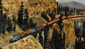
One of the operating challenges is “The Glow Worm”, an eighty cars short tank car train. This train will not fit in any siding, nor is it to be run by less experienced operators.
The layout is to be open for the Rocky Ops weekend. The crews are currently working on fine tuning the railroad and jobs for the visiting operators.

The Ski Train makes an appearance as Rapido Trains produced a Ski Train in the past and requested the Museum make up a video of the equipment in the mountain scenery of the layout. Locomotives wear out quickly on the layout as it is a long layout and runs six days a week in the summer.
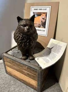
Other items in the museum include some railroad memorabilia. “Dirt the Cat” has a bronze statue displayed at the museum. This is the shop cat found for many years at the Nevada Northern Railway in Ely Nevada. When the cat passed, three bronze statues were cast, and the museum was the recipient of one. There is a full-size Colorado and Southern caboose displayed. The Lionel train wall display is found at the museum. In addition, a Department 56 collection was donated to the museum and is in part displayed. Hopes for the future include expansion where the entire collection may be displayed. The Caboose Hobbies equipment display is located at the museum, including the aprons, photo of the building, and the historical collection that was in the store. A modest size Lego layout is found at the museum supplied and maintained by the local Lego users’ group. A newer addition to the entry are statues welcoming one to the museum and railroading.
Special events are hosted by the museum regularly to entice the public to visit and share the experience. A small N scale layout is on-site with a larger layout in storage. The expansion would include space for this layout and in the future a garden railway to expand the museum offerings and interest for the public. A youth program to build T-Trak is on display. The museum is hosting an RPM meet this September for one day. This is an organized show and tell with rail modelers showing their efforts and discussing the tools and techniques used to build and detail the models. It is open to all modelers and all scales.
The museum has a building that was donated for their use. It was a warehouse building and is not suitable for public use. There is planning in progress to see how this could fit the museum and if it can be repurposed or needs to be razed for a new structure.
The final item on the agenda for the presentation was a video of the local cab train ride through the layout. This is a ¾ scale representation of a diesel cab with the throttle and brake tied to the locomotive on the model rails. This runs the visitor through the layout and shows the total layout trackage in the view screen. This gives the visitor a look at hidden scenes on the layout and a really interesting ride. This may be offered to the public later. Currently the volunteers see this as a track inspection device. The only real drawback is that the tunnels are not scenically modeled inside.
The modelers will add whistle signs to the grade and station signs either on the signal box or on separate signs. Questions included the track code used which was code 83. Mainline switches are all hand laid. The layout was DCC controlled from the beginning. When insufficient operators are available, the layout can run on Auto Ops. This is an electronically controlled operation that controls the trains for operation in the absence of an operator. The rockwork is hand carved or cast throughout the layout.

February Clinic 1 – February 19, 2024
Hospital Trains
Gerry Glancy Biography

Born, raised and educated in California, fortunately in an era when public schools were high quality and enjoyed wide public support. Graduated from medical school in 1966 at which time (Viet Nam) a special set of laws covered physicians. The vast majority of new grads faced a two-year military commitment in some form or other. So, he signed up for two years to “get it over with”. Fourteen years of active duty later he was still “getting it over with”. It was actually the US Army that sponsored his training in pediatric orthopedics surgery. Finally deciding geography was more important than furthering his military career, he settled in Denver and joined the staff at The Children’s Hospital. Ironically, he retired from the same location he had trained in orthopedics, Fitzsimons. Now watching 7 grandkids grow up with the satisfaction of knowing he’s able to facilitate some of their adventures, including model railroading.
Heavy loads of wounded landing at U.S. ports to distribute patients for their rehabilitation to multiple military hospitals throughout the country. This includes Fitzsimmons located in Aurora.
This presentation covered the design and construction of hospital trains primarily during WW 2. The use of hospital trains began in 1854 with Battle of Balaclava, during the Crimean War. The use was expanded during the Civil War by using passenger cars to transport the wounded. In WW 1, the cars were refitted to carry wounded on litters, and nurses to care for the wounded. The friendliness of the nurses was questioned by the presenter, but it is doubted that he had any firsthand experiences during this period.
World War II ushered in a revised scheme of care for the wounded. They were first sent to a battalion aid station to receive initial care. The next stop was the field hospital for additional treatment. The wounds were not closed for a period of 5 days to allow infection to declare itself. This method of treating battle wounds extended to the Vietnam War era. Back to WW II, the hospital trains started in Europe to transport the wounded to the ports to return home. The trains were not fancy, just rehabilitated boxcars or other rolling stock traveling on hastily repaired railroads. Travel was dangerous as the rail lines could be damaged by raids. Weaknesses in the system could be found by the loaded trains. At the European ports, the wounded were loaded onto hospital ships. These were not Navy ships but rather converted Army troop ships, twenty-four Army ships in total.
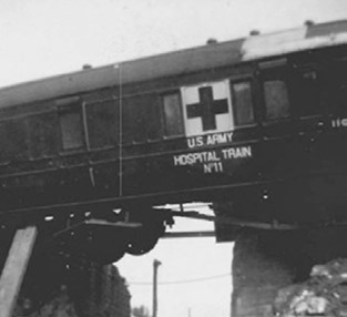
After sailing homeward, the ships landed at one of five ports, New York, Hampton Roads, Charleston, New Orleans, and San Francisco. The hospital train took the patients from the ports to hospitals located around the country, generally to get the patient closest to home, but also the facility was selected to offer the appropriate care for the nature of the injury. Burn victims were sent to San Antonio for treatment. For hand injuries Valley Forge was the leading center for treatment. Along with the wounded, the combatants were also fighting disease. Malaria was one of the common aliments but during WW II tuberculosis was also a major aliment. Fitzsimmons Hospital was specifically built for the treatment of tuberculosis.
At the outset of WW II, no hospital trains were available in the U.S.. The initial solutions were not really solutions. The Pullman cars could not be easily modified to handle litter patients. The dining cars that were a part of the passenger system were not flexible in diet, cleanliness, or scheduling to handle the hospital passengers. The solutions were to utilize army troop train kitchens for the meal preparation operated continuously for the hospital cars. Three special ward cars were designed. One was a ward with only 32 patient capacity on two tier berths. This had wide doors for loading and unloading. The star of the army cars was the Unit Car. This was a train within a train. It was equipped with 3 tier berths for 30 to 36 patients. The car contained a kitchen for food
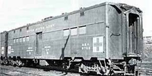

preparation and a pharmacy. It also had two roomettes and toilet/shower facilities. This car could operate singly or as a portion of a hospital consist. All of the Army hospital cars were air conditioned.
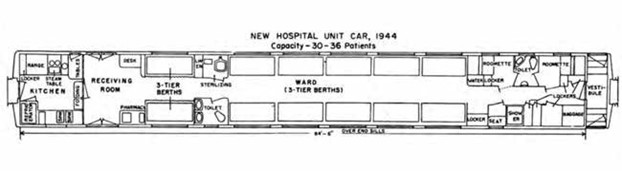
The special berths in the unit car were for psychiatric patients. This is an aspect of combat that carried different terms for the escalating conflicts. In WW 1, it was termed Shell Shock, and in WW II, termed Combat Fatigue. The term today is Post Traumatic Stress Disorder, PTSD. The British had similar hospital trains, but with differing language. The trains were organized with a set number of ambulatory seats, bunks for litters, and 1 to 2 padded berths for the combat fatigue patients.
Finally, there was the question of staffing for the train. Initially, the cars were crewed by staff shanghaied from the port hospital. This left the hospital short staffed, so a permanent detachment was formed for the hospital trains. This staff was one to two doctors, one nurse, and 5 to 6 army medics to care for the patients.
To make the system work, the debarkation hospitals basically dispatched the trains. This was an anticipation of the needs and a determination of the destinations. The trains would be from a single unit car to an 18 car train. The trains would be made up of unit cars and ward cars in a fashion to allow the division of the train at junction points to allow the patients to be directed to their treatment hospital. The routing was determined to minimize the dead head moves allowing the back haul of the train to redistribute patients to additional treatment facilities or local hospitals. It helps to remember that the strength of the U.S. military is logistics, and this was simply a logistic solution. The railroads that participated in the exercise basked in the glory of the Army system.
The hospital trains drew from a list of equipment including 120 Pullman conversion cars, 128 ward cars, 202 unit cars, and 60 kitchen cars. This equipment was used on 40 hospital trains on any given day. The results were from May 1945, when 47,044 patients were moved, and the total for the conflict was about 500,000 patients. The numbers were not easily determined for the total movements as the beginnings of the service were on makeshift cars. General Eisenhower took time to recognize the hospital train moving through his hometown of Abilene, Kansas after VE day.
February Clinic 2 – February 19, 2024
Scratch Building with Monster Modelworks Brick Sheet
Glenn Gibson Biography

Glenn Gibson was born in Dallas, Texas, but grew up in the small town of Plattsburg, Missouri, just outside of Kansas City. Glenn’s dad was the International Harvester dealer there, which provided Glenn with summer employment during his teenage years – mostly working the parts counter, but also performing some character-building activities like sweeping out the shop and occasionally helping unload farm equipment from a flat car at the town team track. Glenn attended the University of Kansas in Lawrence, receiving his Bachelor’s and Master’s degrees in Aerospace Engineering. Following college, Glenn went to work at McDonnell Douglas in St. Louis, Missouri. There he met and married Jane, who for some unfathomable reason is still with him after more than 43 years. In 1979, Glenn & Jane moved to Denver, and Glenn went to work for Martin Marietta. Glenn spent many years performing shock, vibration, acoustic, and loads analyses for various rocket programs with Martin Marietta/Lockheed Martin/United Launch Alliance. He wrapped up his career as an integration manager responsible for ensuring NASA and Air Force spacecraft were mechanically, electrically, environmentally, and functionally compatible with Atlas and Delta launch vehicles. Glenn participated in rocket launches from both Cape Canaveral Air Force Station and Vandenberg Air Force Base. Probably the most exciting (and nerve-wracking) was NASA’s Mars Science Laboratory mission, which placed the Curiosity Rover on Mars. Following retirement, Glenn & Jane moved from Conifer down to Lakewood, and Glenn became a member of the Front Range Division of the NMRA, and the Lockheed Martin model railroad club. In addition to model railroading, Glenn enjoys taking classes on a wide range of topics through Osher Lifelong Learning Institute (OLLI) at DU, and he hopes he and Jane will be able to continue traveling.
Another title for the clinic could be “Constructing a Women’s Boarding House Suspiciously Close to the Railroad Tracks in Salida, Colorado.” Glenn is using material from “Monster Modelworks” which includes wood embossed sheets with a brick or stone pattern. The Monster’s come from Larkspur, Colorado.
The building that Glenn has constructed is a brick building. During a long period of time, from 1939 to 1960, the building was stucco faced. The Scenic Line Modelers layout is set in the 1920’s or the 1940’s, so the modeler can choose the brick façade. The building itself is unremarkable other than the fact the Scenic Line Modelers layout has limited space for town development in Salida and this structure could be placed in a near prototypical location. The small structure across the street from the modeled interest is another Glenn model of the structure noted in public records as a “female boarding house”. Further investigation revealed that almost every building on the block was noted as a “female boarding house”. For the model railroad, the “red light” district of Salida is well represented.
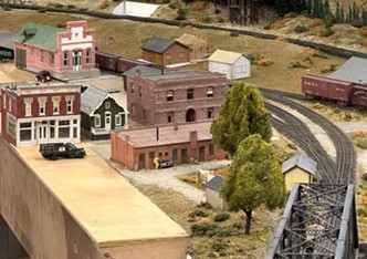
Laura Evans was a madam in the district and during the Spanish flu, she provided beds for the ill after suspending operations for that period. Further, she provided food and coal during the Depression years to those in need. She provided social services in Salida prior to the term being popularized. The county district attorney drove the operations underground in the 1950’s.
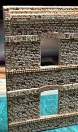
Monster Modelworks is a division of Larkspur LaserArt. The products are available in N, HO, S & O scale in a variety of patterns in brick, block, and stone.
The material is 1/8 inch thick and 1/32” thick. This allows the basic structure to be constructed in 1/8” material with the details added in 1/32” material. The beauty of the system is the availability of the arched frames, corners, columns, sills, lintels, coping, and cornices. This adds a level of detail to the structure.
The reasons for using this product for this building project was that no plastic kits were identified to kitbash for the structure; the prominent arch over the main door was available; the old brick sheet product from Monster was available to represent a brick wall in poor shape that basically needed the applied stucco finish at a later time; and Glenn had used the concrete block sheet on a previous modeling project.
The windows for the project were not commercially available, so Tichy Train Group windows were modified to make up windows matching the Google Street View images of the building. Working with the images and the window sizing
chosen, the overall building was estimated at 40 feet wide and 28.5 feet high. This scaling provided a good-looking structure. The sides of the building were more difficult to model as the current photos show the side windows bricked over. Again, estimating from the available photo, the side windows were narrower than the front facing windows. The side dimension was shortened to fit the model space and the wall steps were scaled in to fit the building look and feel. Both sides of the building were made the same. The rear of the building today has no doors or windows, but during the model era it was assumed that there was a rear door and some small windows for bathroom areas.
Building the structure required transferring the dimensions and openings to the back side of the sheet. The cuts were made, and openings squared up with sanding sticks. A circle cutter compass was used to cut out the arch to match the arch lintel. The windowsills, lintels, cornice and other trim parts were added to the outer walls. On the back of the building, the one opening ended up too large for the window treatment, the opening was filled using the clean brick sheet. This gave a different texture to the wall and the effect was used on two more windows.
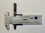
The brick was initially painted with Rustoleum 2X Flat Red Primer. Roberts Brick Mortar Formula was thinned and used to highlight the mortar joints. This treatment is wiped off after a short drying period, but some trim parts buckled. The foundation areas were painted with Rustoleum 2X Fossil, which is a good representation of old brick. The roof was constructed of 1/16” basswood. This was covered in first aid tape and painted with Krylon dark brown camouflage. The Monster system includes column material which was used to fashion the chimney. The soil pipe was modeled with brass tubing. Window frames were painted with Rustoleum 2X Nutmeg with windows installed with canopy glue. The curtains were modeled from Window Designer software. The front wall windows have a stained glass panel above the clear pane window. The stained glass was modeled in PowerPoint and printed on transparency film. This adds to the distinctive look of the building.
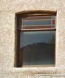
These sheet products and details are available at: https://larkspurlaserart.com/monster-modelworks/
Check them out for your modeling needs.
February Clinic 3 – February 19, 2024
Trees, trees, and more trees
Rich Gibson Biography
This was the floor show portion of the clinics as Rich moved to the center of the room for a demonstration. Rich models the New England area. This requires a lot of trees on his layout, and he points out that he cannot spend much time on individual trees. He uses natural materials as he can get a good variety of shapes and forms from the materials that cannot be duplicated with commercial products. As this is primarily deciduous trees, the focus is on natural armatures with the shapes common to the desired model tree.
| Plant | Flock Size | Adhesive |
| Super Trees | Coarse Turf | Matte Medium |
| Oakleaf hydrangea | Coarse Turf | Spray Adhesive |
| Nandina | Underbrush | Spray Adhesive |
Other plants can be used as well; Crepe Myrtle, Sagebrush, Saltbush, Sedum, Goldenrod, Rabbitbrush. The key is to find material that the modeler finds suitable and experiment to make up your forest/tree. It is helpful to source the materials in the locale, so the supply is readily available.
The Supertrees material is purchased as a component or a kit. The component method allows more flexibility by the modeler to adjust the texture and colors for the trees.

Oakleaf hydrangea is an ornamental flowering plant that will grow in this area. The piece that the modeler desires is the flower head. After drying, the flowers may be stripped off and the resulting armature may be trimmed to the tree shape desired.

Nandina is an ornamental plant very common in the Tulsa area. Rich takes a box and fills it on his trips to the Tulsa area to insure his supply. The plant has two strikes against its growth on the Front Range of Colorado. Some varieties of the plant are considered invasive particularly the fruiting plants. Further, the plants are not winter hardy for much of northeastern Colorado. The fruit stems are the modeling material. For the tree armature, the berries and other vegetative matter are stripped off. The resulting armature can be trimmed to shape.
The key to making realistic trees is to match the size of the flocking material to the armature and to select the adhesive to match both the flocking and the tree armature.
Rich demonstrated his technique for making the tree from the Hydrangea. He selected a stem, removed the remaining flower petals, sprayed on 3M 77 adhesive, and sprinkled on the Woodland Scenics coarse turf. The tree was completed in 1 minute and 20 seconds during the demo with the explanation of what he was doing and getting the materials out of the storage container. Some stems have little pods attached and those are best combed out or picked off as they will show through the flocking.
He stepped into the tree process with Nandina. These stems are much tougher than the Hydrangea. Using a technique similar to the Hydrangea, pick off the remaining berries and remnants. Trim and paint the stem to form the armature. Spray the armature with the 3M Super 77 adhesive and sprinkle on Woodland Scenics underbrush as the flocking. A key to using these trees is that the base or bottom may not look the best, but in mass plantings, the lower part of the tree is obscured.

Supertrees need a little more preparation. When the modeler receives the box of Supertrees, it contains the remains of a “Norwegian Sagebrush”. These pieces have a good tree like structure but are oftentimes bent or curled. They need to be separated into model tree size stems. The stems contain small leaves. The leaves need to be removed. Don’t discard the leaf bits as they are useful in other modeling. The leaves can be used to model harvested corn fields and other small branch bits can be used to make underbrush and small trees. The armatures are best soaked in dilute mat medium and then suspend them vertically weighted to enforce a straight trunk. After drying, the armatures may be painted a grey color or other colors to model natural tree bark. To apply the flocking to these armatures, the branch structure is rolled in diluted mat medium keeping as much of the trunk out of the medium as possible. Sprinkle the coarse turf flock on the branches to the desired thickness. The resulting trees have fine branch detail and are suitable for foreground trees. The trees should be suspended upside down to fully dry.
To add fall colors to the trees, use a completed flocked tree and overspray the tree with cheap hairspray from the top down. Sprinkle the tree with fall color leaf flock in a straight color or mixing colors for variety. Overspray the tree again with hairspray to fix the colored flock. This technique can be used to add summer “leafy” appearance by adding slightly differing colors to the crown of the trees.
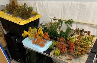
The modeler will need a selection of trees to add to the layout. Rich makes a lot of trees and stages them in foam or boards drilled to accept the trunks. A variety of material makes for a variety of tree types to add to the layout in an area. These are the trees ready to plant.

This is a box of small bits and pieces flocked and ready to add to the layout as the under story of the forested area.
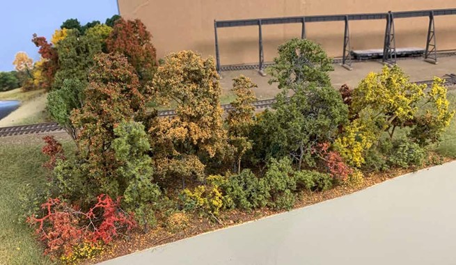
Rich continued the clinic with a discussion of bottle brush trees as conifers for layout use. Spruce and fir trees have a classic conical shape. But pine trees have differing rounded shape profile. The materials that you need for this process is sisal rope and floral wire. The sisal rope is disaggregated into single strands of sisal fiber. These are the branch structure for the tree. For an HO tree, two inch lengths of sisal are used. This length can be adjusted for differing scales and differing masses of trees. Spread the fibers between the two lengths of floral wire anchored to a vice or in a tree jig. Twist the wire using a drill or the tree jig to anchor the sisal within the twisted wire. Cut the wire into tree length pieces with variations for differing height trees. One good point with this method is the branches can easily be trimmed back or eliminated all together to replicate the damage seen in nature. The trees can be shaped to mimic the shape of the type of conifer tree more closely. After trimming to length, the trees should be painted with camo brown, dark grey or black paint. The spray adhesive can be applied to the branch structure and the branches flocked with fine or coarse turf.
Since the video did not work on capturing Rich’s presentation from the floor, a separate time is being worked on to video Rich showing the work portion of the Tree presentation.
January Clinic – January 15, 2024
Modeling the ATSF Built Cars of the 50’s and 60’s
This clinic looks at many of the thousands of ATSF built and rebuilt cars of the 50’s and 60’s and some of their unique characteristics not found in commercially produced cars. We will look at some kit bashing techniques, added details, use of rivet decals, painting and lettering to represent these cars. Most of the kit bashing is commercial plastic kits and parts. The cars that will be discussed are boxcars of varying lengths as well as reefers.
Denny Krausman Biography
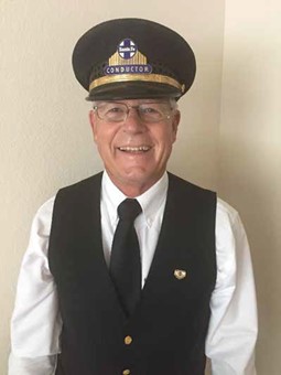
Denny was born and raised on a farm in central Iowa and received a BA Degree in Physics from Northern Iowa and later received an MBA Degree from the University of Colorado. He spent nearly 50 years in the Heavy/Highway construction business and retired several years ago.
Denny has been a member of the Santa Fe Railway Historical & Modeling Society (SFRH&MS) for nearly 30 years, and he models the Santa Fe RR in southeastern Colorado in HO scale with the time period of the late 60’s and early 70’s. He is a recent recipient of a Master Model Railroader Certificate #622.
During the past 40 years of modeling, Denny has built scratch-built models and a number of resin craftsman kits, as well as a number of kit-bashed cars. One of the things he enjoys most is researching prototypes, so he can accurately model what he is building. This has helped Denny to build a number of award-winning models. He has given a number of clinics on these topics and has been published in the SFRH&MS Warbonnet, NMRA Magazine, and Railroad Model Craftsman.
The January meeting for the Front Range Division was held via Zoom. The weather wasn’t kind to the group. Denny Krausman shared his presentation on Modeling the ATSF Built Cars of the 50’s and 60’s. As been noted several times, the second world war was hard on railroad equipment. The railroads needed new power and importantly new boxcars to handle the post-war boom in freight. With that in mind, the ATSF began a program to construct and re- build their car fleet. As an ATSF modeler of that era, Denny researched the Santa Fe cars and noted that the ready-to-run or even the kits offered did not match the photographs and builder plates, or car plans. To get the cars that he wanted, he set about assembling his model fleet from kit parts, individual parts, and by casting some of his own parts to make up the cars he wished to model. The Santa Fe community has several color and black and white photography books covering the cars of the era. The Santa Fe Modeling and Historical Society has a treasure trove of information on the railroad and its history.
The ATSF had over the war years beefed up their car shops to keep up with fleet maintenance. After the war, car manufacturers could not satisfy the demand for new cars. The Santa Fe determined that with the shop capacity they could build their own boxcars as the parts were available. As illustrated in the chart, the Santa Fe Railroad built most new cars or re-built cars in-house. The chart also shows the transition from 40-foot cars to 50-foot cars as the years progressed.
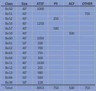
Their preference was to utilize riveted construction. They purchased 750 Pullman Standard boxcars, PS-1, under the program but they were not satisfied with the welded construction, so they continued using standard riveted construction. As the clinic progressed there was a question on the use of riveted construction. At this point, it is still an unanswered question. The Santa Fe Railroad persisted in the use of riveted car construction into the 1980’s.
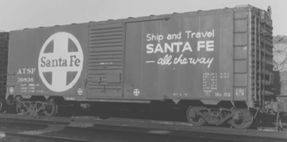
Santa Fe’s new standard boxcar, the Bx53, was a forty-foot boxcar with 4/4 improved dreadnaught ends, diagonal panel roof, lightweight Youngstown doors; and 12 panel sides. These elements were common to the series of box cars with the difference being the width of the doors and added panels to lengthen the car. Few commercially available models are available in this configuration. As was noted by John C. Bobyne III in his book, the use of improved dreadnaught ends in combination with diagonal panel roofs was common in Canada but not in the United States. It could be argued that the Santa Fe Railroad made this combination common in the U.S. as certainly 9000 cars noted on the chart is a large number.
Denny was not deterred by the lack of commercially available models. He made a mold of the 4/4 improved dreadnaught ends from Branch line Trains and was able to cast as many as the mold would allow. The start of the car build was an Intermountain 12 panel box car kit. The roof was changed out to a diagonal roof at the time available from Branch line Trains, cast ends roughed out the Santa Fe version of the box car. Rounding out the car were doors and roof walks available from Kadee. After painting and decaling for the period, the result is a very nice prototypical car.
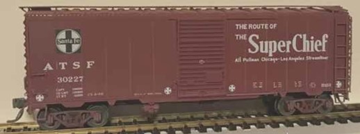
This process was continued for each individual car basically kit-bashing the car from an assemblage of parts. The beauty of the system is that the modeler can craft the model fleet to the period of the model era, and the number of the types of cars can be proportioned to the Santa Fe constructed fleet.
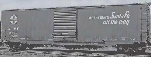
As time progressed, the construction efforts turned to 50-foot box cars, as the Bx66, above. These cars were 16 panels long with riveted construction. The cars shared the details of the 40-foot cars with 4/4 dreadnaught ends, and diagonal panel roofs. The doors were increased to an 8-foot-wide door. Added on each side of the door opening were diagonal braces from the outside edge of the adjacent panels to the door opening above. Riveted gussets at the lower edge of the door opening were added. These changes added some detailed elements to the car. The diagonal rivet lines can be added with rivet decals. The gusset plates are added pieces of styrene again with added rivet decals to complete the look. Moving to re-built cars we find the Bx39. This car was a war-emergency box car with wood sheathed sides. The car was intended to be re-built with steel sides at the war’s end. Santa Fe re-built the car with 16 panel sides, an 8-foot door, and the reinforcing details of the Bx66. One difficulty encountered with modeling this car is that since it was constructed early in the war period, it utilized 5/5 standard dreadnaught ends, which have a definite differing appearance from the 4/4 ends. An additional detail was a plate added at the car end to attach the stirrup step. For this series of cars, Branch line Trains produced a kit that had the characteristics of the Santa Fe car. This kit includes the spotting details of the 16-panels, 8-foot door, and an added plate for the end stirrup steps. The car included 4/4 improved dreadnaught ends which needed to be switched out for the 5/5 standard dreadnaught ends.
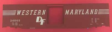
Adding the rivet lines on car was accomplished with Micro Mark rivet decals. The Micro Mark version of the rivet decals is a little larger and more pronounced, so after application and painting the detail matches the cast details of the cars.
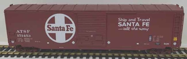
This produced a great-looking Bx39 model to add to the fleet.
Using the same Branch line kit, the modeler may produce a Bx61. This example of the car is unique as it has white doors and the XF decal in the corner indicating that this is for food-loading only.

The profile at the ends of the car is somewhat different as the stirrup bracket plate is omitted. This detail was trimmed off the car body and the stirrup step sets back from the face of the car a slight amount.
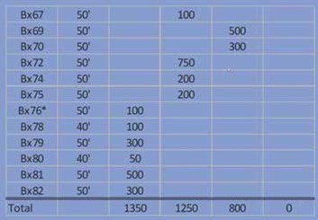
In the late 1950’s, Santa Fe continued to purchase 50-foot cars from other manufacturers. The reason for the break in shop produced cars was that Santa Fe was retooling for the construction of their version of the shock control underframe cars. This adds new details and yields a different look to the cars.
The 50-foot cars from the Bx76 forward were all cushioned underframes. This car had a different side sill appearance. For this series of car models, the car sides were cut from styrene sheet. The total rivet detail configuration was applied with decals. The upper edge of the car was decorated with an additional styrene strip to match the prototype. The doors were glued in place. The sides were primed prior to rivet decaling as the decals need the tooth of the primer coat to adhere to the styrene. Basically, the car is just a box fitted to the frame. Tangent Models made a shock control underframe, and this was used on this project. The painting on this car is two-tone with the sill and upper car edge black with the remaining side red. The ends and the roof are painted black. Another element on the car is the SL logo in a circle at the end of the car. This decal was only available from Tichy.
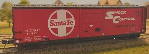
This is a very distinctive model that really adds to the Santa Fe feel of the car fleet.

The car construction continued on with building and re-building of 40-foot cars. The Bx83 was a re-built 40-foot box car with a super shock control underframe. These cars were all dedicated to appliance delivery service to reduce freight damage during shipment and handling. The cars were equipped with 8-foot doors to facilitate loading. The result was a unique car.

In another customer-driven car type was the Bx85. This car is a rebuilt Bx12 that was given a new life in grain delivery service. The car sides were built with riveted construction and a plug door with grain inspection doors built into the plug door. While the industry was transitioning to covered hoppers for grain service, many of the Santa Fe elevator customers were not equipped to handle overhead delivery of the grain. These box cars were used to ship grain from the large number of small operations. To model these cars, one needed to find frames and floors built on the narrower dimensions of the Bx12. To extend the interior width of the car, an angle was used to place the sides at the wider width. To start the project, a Central Valley stock car frame was used. This has a narrow width to form the base of the car.

The car sides were built with styrene sheet to the dimensions needed and framed out in a box configuration. The correct end castings were available as Westerfield Models. The plug door was scribed into the sides. The panel rivet lines were marked on the sides. Tangent models provided the door hardware and that was attached prior to painting. The painting was a two-step process with the reefer orange sprayed first. The loading doors were masked off and the box car red finish coat was applied. This finished the car with the correct profile.
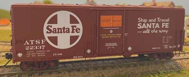
Santa Fe also re-built some of their Bx37 car fleet into similar grain cars, Bx115. Since the Bx37 was built in later years, the width of the car was appropriate. The cars sported reinforcing gussets on the sill of the car, basically three near each bolster point. The starting point for this car is a Branch line kit, 40-foot, 10 panel box car. The doors were scratch built like the Bx85, and the car painted with a two-tone paint scheme to highlight the grain doors. The bottom of these cars had a straight sill line and so the detail on the kit was removed and a styrene sill was added.
In the late 1960’s, Santa Fe built a new style of box car, the Bx94. This car had exterior bracing and wide plug doors. It was another in their series of shock control cars.
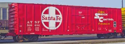
Moloco Trains made a copy of both the Bx94 and Bx97. They were good enough to pass for the cars and it was a matter of purchasing them.
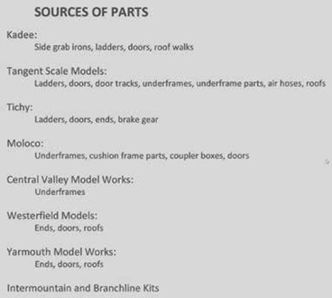
As we went through the presentation, several parts sources were noted. Some of these sources are still good but several of the suppliers have merged into larger companies and the products are no longer available from them. It is important to source parts as available at train shows, swap meets, hobby shops, eBay, and other on-line sources. One needs to be careful shopping on-line because of unscrupulous operators.
While this clinic has focused on box cars, Santa Fe rebuilt several other car types. The reefers were updated by the shops. The RR19 for example was re-built to a more user-friendly car. The icing hatch doors were modified to flip open to the center of the car. Drains were added to the ice bunkers to prolong the life of the car floor. Reinforcing plates were added to the sill. Doors were updated or remained the same. So, there is another clinic on the history of the Santa Fe reefers. Also, Santa Fe rebuilt gondolas, and flat cars. So, expect more to come! The questions were asked on the reason for the grain door box cars. This was customer accommodation. Smaller elevators could not afford to update their loading systems to top load covered hoppers. So, for those customers the railroad made available the plug door versions.
Denny was also asked how many cars he has on his railroad. He has around 300 cars of all types. More are needed to round out a representative fleet.
Clinics for 2023
December Clinic – Gathering of the Elves
December is the time for the Holiday Gathering of the Elves. This is a pot luck event, so it is time for the party recipes to come out of hiding and make an appearance. Start planning your contribution to the festivities. As is usually the case, chocolate desserts are preferred. Be sure to attend the November meeting to get in to the menu planning.
The Front Range Division holiday party will be held Saturday, December 9th, at 6:30 pm at Rich Gibson’s home (address and map below). Spouses, partners, or +1s are welcome. Janet and Rich will provide an appetizer, a dessert, soft drinks, mulled wine, and some beer. Please bring an appetizer or dessert to share.
Rich’s layout will be open for your review and adoration.
For planning purposes, please let Rich know if you will attend with the number of guests by December 4th to richgibson89@yahoo.com. Please join the Front Range Division for an enjoyable evening of model railroading fellowship.

As is the usual custom of the Front Range Division, the December meeting was a Gathering of Elves or a holiday party. Rich Gibson and Janet Schweitzer hosted the gathering at their festively decorated home. They also provided food to enjoy with a ham, Hawaiian sweet rolls, and drinks to enjoy. The potluck area was filled with other goodies including appetizers, salads, and of course desserts. The most sought-after dessert was the Chocolate Dream Pie which for some reason simply disappeared.
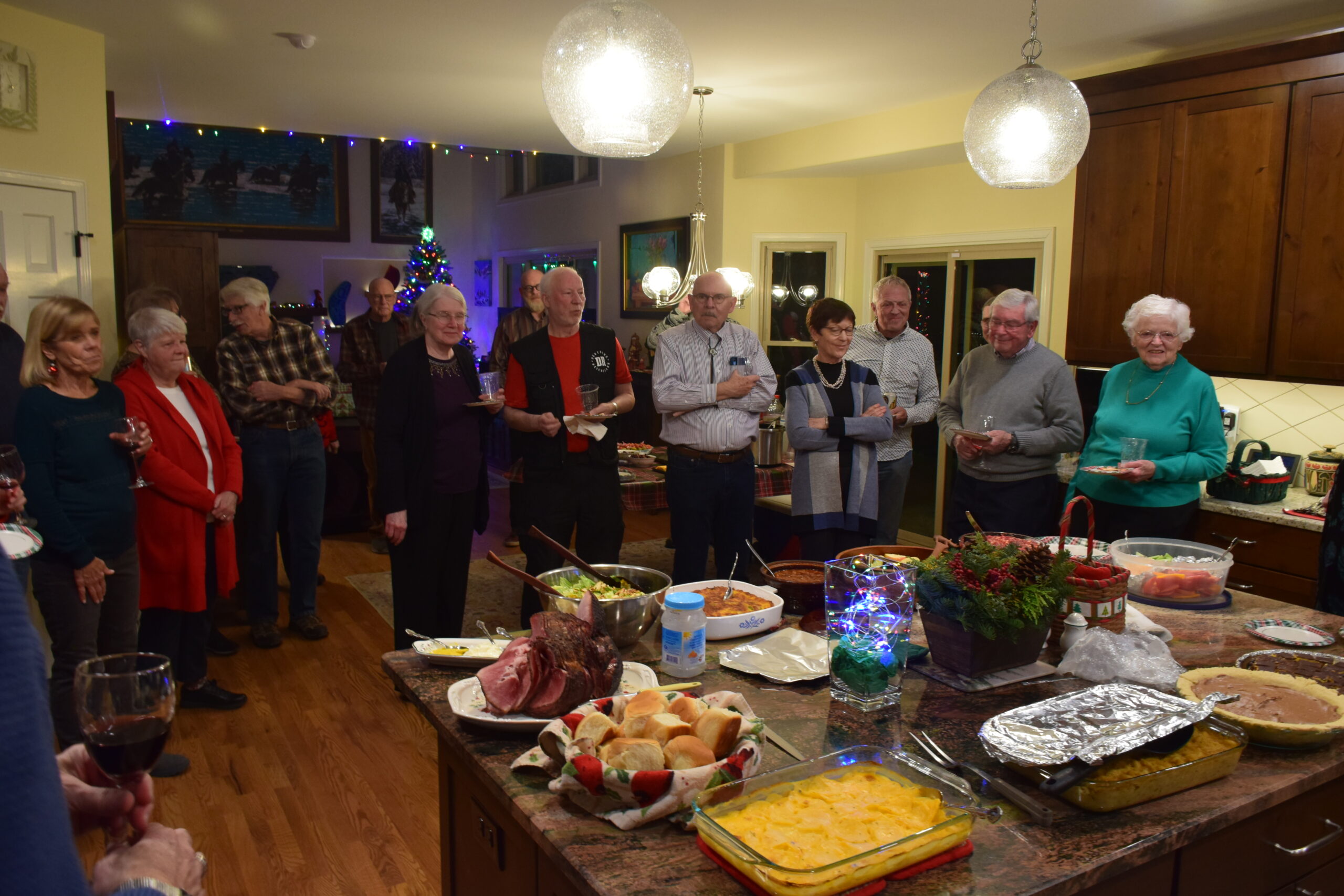
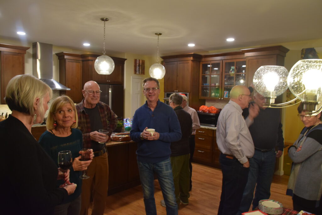
The event was well attended. The Maine Central – Portland Division model railroad was open for visitation. There were two new areas developed since the Division’s last visit a year ago. The Lewiston Branch was enlarged to add more switching action. The staging yard was moved across the train room to the eastern wall. This will give more operating space and more industry development.
A presentation was made to Keith Hayes. Keith earned his Certificate of Achievement for Model Railroad Author. This is one of the achievement certificates on the journey to Master Model Railroader. Congratulations to Keith for the milestone and keep up your good work.


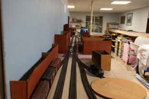
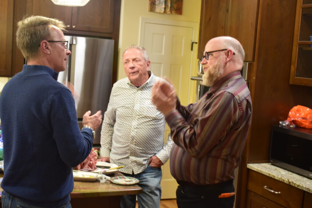
November Clinic – November 27, 2023
1st Mini-Clinic of the Night
Glenn Runkewich Biography
Glenn grew up in the railroad town of Cheyenne, Wyoming. As a boy, he would ride bikes with his friends down to the Union Pacific tracks to watch the mile long trains coming and going from the famed Sherman Hill. After
high school, he attended the University of Wyoming on a debate scholarship in Laramie just the other side of Sherman Hill. There, he earned a BS degree in Economics and an MS in Business Administration. He moved to Denver in 1980 and began a career managing software development projects for several large telecommunications firms finally retiring from Comcast as a senior systems architect. During this previous life, he was also an avid white water boater rowing his raft down many of the west’s major rivers including three trips through the Grand Canyon.
Currently in addition to model railroading, Glenn enjoys traveling, skiing, and music. He plays regularly with the Pueblo Drum Tribe, and creates music videos he posts on his YouTube channel. They can be found at YouTube.com/@HowlingCatSoundAndImage. He and his wife Diane split time between Highlands Ranch and their cabin in Northern Wyoming. They have a son, two grandsons, and two very pampered goldendoodles.
Glenn’s mini-clinic will concern the Sylvan Models HO Scale Laker Class Freighter Kit. He will clinically explore the challenges presented in constructing this kit, modification and additions he made, the history of these ships, and online resources available for research on the prototypes.
Glenn Runkewich shared his experiences constructing a freighter model for his layout. The SS Jack Brody started its life as a Sylvan Models HO Scale Laker Class Freighter Kit.
Glenn has been building ship models since he was a youngster and has completed two models as an adult. The ship models are very delicate and should be displayed under a cover. Seeing as how Glenn has a model railroad, he has a good display area for his ship project. The available ship models in HO scale and N scale are very few and are mostly larger models than could be accommodated on the HO layout.
This is a resin kit that follows a prototype ship. The instructions refer to the box top at several points, and many of the details are obscured. This ship is a model of the WW I Laker Class ship which is the equivalent to the WW II Liberty Ships. The United States Shipping Board which during the First World War assumed the responsibility for maritime activities, similar to the United States Railroad Administration. The Board used standard designs for construction of the various classes of ships. Using these standards, ship construction numbered 431 in 1917, 535 in 1918, and finally 1180 in 1919. Of note here, is that production ramped up and exceeded the number of ships needed after the end of the Great War. As this was a government operation, we needed an accounting of the costs of the ships. This ship building exercise employed 350,000, built 8000 houses, 9 hotels, 900 apartments, 21 dormitories, 11 cafeterias, 2 schools, 81 stores, and one hospital. So, the results of the effort was the establishment of a ship-building infrastructure to put the U.S. on par with the remainder of the world.
The model is fashioned after Design 1020, which was intended to be used in the Great Lakes. The Welland Canal Locks were 270 feet long, 45 feet wide, and 18 feet deep. The 1020 was 261 feet long, 43 feet wide, and 22 feet maximum depth. This means the ship could not transit the locks fully loaded but could use the locks empty or with a partial load. It is okay as the war effort would require the fully loaded ships to transit the Great Lakes after the locks and continue to Great Britain. This hull design was used in a number of configurations and between 400 to 500 ships were constructed by the Great Lakes ship builders, by West Coast ship builders, and Canadian builders. The specific design 1020 has several specific features to use as spotting hints. The ship has two masts with ratlines, a walkway in front of the bridge, and a small pilot house. On the interior, two coal fired boilers develop 180 psi in a 1500 HP triple expansion steam engine. This will propel the ship at 9 knots (10 mph) until the fuel is exhausted. At least 35 of these specific configurations were constructed.

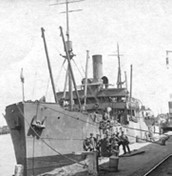
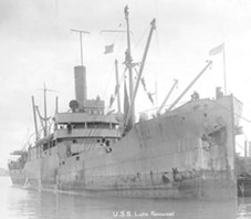
The difficulty is too many ships were constructed, and the U.S. ship building industry collapsed. The ships were sold to many nations and domestic operators. A number could be found on the West Coast working lumber operations. Ford Motor Company purchased 150 ships for scrap. The ships were utilized by all combatants in World War II. The final examples of these ships were scrapped in the 1970’s. From the modeling side, the long life of the ships means it had a 50-year life span of where the ship and the model would be appropriate on the layout.
Since the instructions were a little vague and imparted little history to the layout model, Glenn researched the ships in their use. Photographs were available on the internet of the lake class of ships and showed a number of variations to be considered for the model. The photos showed two or four lifeboats, four life preservers or none, an aft gun platform or not, and antennas were visible on some photos. Using modeler’s license, four lifeboats were modeled including four life preservers on the pilot house. Most importantly, the photos showed the rigging for the ships with pulleys and doubled lines visible in the black and white photos. Glenn went through the rigging for the ship in detail illustrating the complexity.
The modelers’ resources that were used in the kit construction were:
- Kit Instructions: History, Assembly Diagrams
- Internet Images: Prototype Photos, Model Photos, Artist Portrayals, 1020 Plans
- Mainline Modeler Magazine: Extensive History, 1099 Plans, Prototype Photos
- San Francisco Maritime National Park 1943 Deckhand Training Guide: Extensive Rigging Descriptions and Diagrams
The model itself is a blended prototype with features not following any specific prototype. Remembering these ships were constructed by numerous ship building enterprises, many variations were built on the ships and with the long length of service, many modifications and repairs were performed on the individual ships. Some of the items were included to assist in the construction of the model, and others were an application for an artistic license.
The kit is a resin kit, and as such, the detail is not as fine as styrene models, and it is thin meaning it will warp and twist. The kit was assembled and sometimes re-assembled with plenty of super glue. As these kits have a lot of flash and the fit is not exact, a utility knife was used to clean up and carve the kit to allow the build to proceed.
Details were added to the model to add interest in the ship. All rigging was added, porthole glass, scupper bars, stairway rails, light sconces, weather deck braces, ship name, American flag, life preservers, small cowl ventilators, spare anchor, loose cargo, pallets, figures, bridge and pilot deck support posts, boom cradles, modified steam piping, funnel seams, eyebolt plates, chart table, and night lighting rounds out the list of added or enhanced items on the ship. Additional details were sourced from Cast Your Anchor; ships bell, cleats, medium size blocks, and cargo hooks. This is an extensive list, so the ship kit was a starting point for the building effort.
As noted the rigging was explained in detail and those interested should refer to the 1943 Deckhand Training Guide for a full explanation.

Since this model is to be installed on the layout with other lighted structures, lighting was added to the ship in the pilot house under the chart table to disperse the lighting. The light flows into the bridge and further adds indirect lighting to the walkways below. This gives a great nighttime effect.
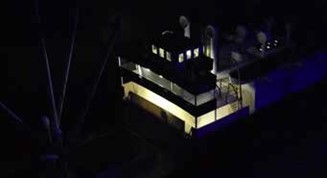
2nd Mini-Clinic of the Night
Rich Gibson Biography
Rich grew up in suburbia on the east side of Cleveland, Ohio and became fascinated by rocks and minerals at an early age. In 7th grade, Rich thought it a good idea to correct his science teacher’s geology errors …. it wasn’t. Rich attended Allegheny College, majoring in Geology, and followed this up by earning an MS and PhD at Virginia Tech. Despite always wanting to pursue an academic career, there were very few positions available when he was graduated. Thus, Rich ended up joining Amoco and worked for them, and their successor BP, for 21 years on oil and gas exploration and production projects in numerous parts of the world. His early retirement in 2010 lasted 2 weeks before he joined Apache. 3½ years later joined SM Energy where he retired in 2023. He and his wife (Janet) tried to get located in Denver in the early 1990’s, but took a rather circuitous route, moving 8 times and finally ending up here in 2016. He has always had a general interest in history, and enjoyed traveling and hiking. However, Rich’s activities over the last ten years have become increasingly rail related.
Rich will continue with the overall theme of the mini-clinics with a short version of “Building Bath”. This will describe his attempt to reproduce the appearance and operations of a crowded Maine shipbuilding town in a limited space.
Rich Gibson continued with his clinic concerning his Maine Central-Rockland Branch which includes a representation of Bath Maine. Bath Iron Works is a major employer in the area and continues to be a military ship building center. During his modeling period, the railroad and the highway were carried over the Kennebec River on a one half mile long bridge. In 1919, the bridge had not been constructed and ferries were used to get trains, passengers, and everything else over the river. The bridge was completed in 1927 and carried the railway and the highway over the river. This changed the river front area of Bath and created opportunities for the railroad and shipyard to redistrict the area for continuing use.
There were some difficulties encountered in modeling a representation of Bath on the Rockland Branch. The first compromise is the Bath Iron Works is represented by a crane and a spur track. The iron works size is too large to fit in the model area. Secondly, the commercial district, of Bath, including the coal dock is rotated to be more perpendicular to the modeled river. This maintains the integrity of the trackwork and keeps the operational simplicity for operations in the area.
One of the signature buildings in Bath is the Maine Central Depot, which was paid for by the U.S. Navy to show a more substantial presence to the visitors to the Bath Iron Works. The model of the depot was constructed by Richard Segal of RightOnTrackModels based on the prototype photos and using the footprint available in the Bath track/bridge area. The depot model ends were skewed to fit the curve, as of course, the modeled curve is much sharper than the prototype track work.
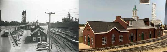

To the right of the historic photo is the highway bridge being elevated to the lift bridge. This signature portion of the scene was modeled using gator board, PVC pipe, styrene, and insulating foam to build up into a realistic bridge. This structure forms a view block for the track to continue through the backdrop.
The next major item was kit-bashed for the Bath area is the shipyard crane. The crane was an amalgamation of the TYCO Gantry Crane and the Walthers Pier and Traveling Crane. The Walthers crane was too large for the scene and the TYCO was just not right for the scene. The TYCO gantry portion was utilized with the Walthers crane boom and engine house. The engine house was shortened to fit the gantry base, and the TYCO crane boom was re-purposed as the vertical jib. This yielded a substantial crane fixture in a small footprint. It is rail carried to move for loading and unloading.

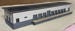
Continuing on the build out of downtown Bath, we come to MEC freight house. This was a long structure in Bath which was shortened for the model area. The building includes a large number of doors each one adjacent to another. The structure was constructed of bass wood with a nice uniform roof line.
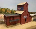
The elevator on Commercial Street was the next undertaking of the Bath modeling. This building was a combination of a Campbell grain elevator, shortened to make it more typical of a New England style elevator, and a Fine Scale Miniatures portion of a kit. This gives the structure more width along the street and adds to the business feel of the area. It also adds a covered dock area at the street.
The next bit of the commercial district is the Pipe Company and the Torrey Roller Bushing Works. The Pipe Company was noted on one of the early Sanborn maps as the pipe company and was later noted as a water works building. The Pipe Company is a nice square building with a flat roof. It was constructed from bass wood structure braced to prevent warping.
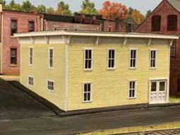

The Torrey building complex was a combination of four eras of construction with differing architectural detailing. The portion with the most interest is the part with arched windows set in the brick walls. The next sections had rectangular windows with differing styles. The arched windows were the most desirable feature to model. Model Builder’s Supply Line, now under the N Scale Architect line, has a building wall system which includes arched windows. The kit includes a brass sheet of window details that the modeler cuts and folds to make up the arched windows and the mullions within the frame. The kit includes brick facing material that can be cut into the building wall shape. This formed the basis for the arched window portion of the structure with the square windowed areas built with Walthers windows from the scrap box. (No, we do not know what kit they came from.) The prototype building had four sections, but the modeled structure was modified to three sections to get the feel of the stepped appearance of the structure.
Another business to model in Bath was Prawer Wholesale Grocery. This was a rail served grocery warehouse that unloaded the products from boxcars and refrigerated cars and moved them across the street into the business. This gives an opportunity to drop more cars on the street. The building was put together from a couple of photos and sized to fit the area available on the layout.
Wrapping up the commercial business area of Bath, we have two unique businesses. The Acme Supply Company and Nadeau’s Garage. The Acme building was constructed from a single photo, squared up and sized to fit at the end of the street. It was a basswood building with scrap box windows and doors. The interior is yet vacant as there needed to be washers and stoves added to the display. The rockets and explosives are sold out of the back of the building. Nadeau’s Garage is a shady looking operation probably subsisting on small engine repair and service.
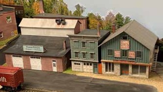
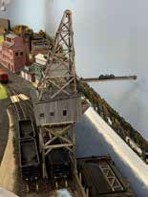
The final structure completed to date for Bath was the coal pocket. Again, this is a space constrained item and area. For this a box of sticks was purchased with a large coal pier. The item was intended to model outbound coal shipments. The rail cars were to be unloaded and coal transferred to ships or barges. In this instance, the coal is inbound, and the gondolas are at grade. Part of the kit was used to construct the Bath coal pocket. The height was reduced, the derrick and boom were shortened to make it believable, the head house and powerhouse were combined and constructed of gator board with wood siding sticks applied. The coal chute was centered over the structure and tracks.
This is the resulting overview of Bath.
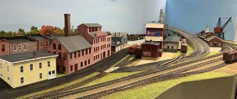
Since we are model railroaders, there is always more to add to the scene. A crossing tower is missing to control the traffic on the tracks. A unique scale house must be constructed to fit the scene. This structure appears like an elevated covered bridge over the scale track to weigh primarily the coal hoppers. The customs house needs to be outfitted to match the existing customs house in Bath. The primary emphasis will be to modify the roof lines and ornamentation. The coloring will be changed to the white tone of the existing building. Lastly, a collier will need to be constructed to service the coal pocket. This is a difficult build as it must be about ½ of a ship model and much shorter in length than the available models.
October Clinic – October 16, 2023
Due to an unfortunate scheduling difficulty, the regularly scheduled meeting was unable to meet in the usual room and was canceled. The clinic, which was schedule “How Fred Harvey Opened Up the American Southwest” by Christine Petty, has been rescheduled for Monday, January 15, 2024. The next clinic in the schedule has also been moved from Monday, November 20, 2023 to Monday, November 27, 2023.
September Clinic – September 18, 2023
The Denver and Rio Grande Western – Monarch Branch
In this clinic, Gary Myers will review the evolution of the Monarch Branch and its importance to the Colorado Fuel and Iron Pueblo Steel Mill. This branch started as a narrow gauge rail line to the mine near the summit of Monarch Pass. The route utilized two sets of switchbacks and grades up to 4.5%. The line was operated seasonally most years from May to November. In 1956, the track was converted to standard gauge and extended to Salida. This removed the necessity of transloading the ores at a unique rotating barrel in Salida.
Gary Myers Biography

Gary Myers is currently living in Aurora with his wife, Michelle. They have two little 7 year-old Shih-Tzu brothers, Thor & Loki. His son Alex is 31, and lives in North Detroit. Gary is on his 5th Ford Mustang, a yellow 2005 GT.
Gary grew-up in Michigan, and graduated with a BA in Aerospace Engineering at the University of Michigan. From 1981 to 1985, he lived in the Bay Area – Sunnyvale, CA., and worked at Lockheed Missiles and Space on spacecraft and Titan 34B launches from the Blue Cube (later Onizucka AFS).
He moved to Denver in January 1986 and has been here ever since. He worked at Martin Marietta, Lockheed Martin, and United Launch Alliance until 2016. His worked involved trajectory analysis for Titan IV, Titan II, Atlas IIAS, Atlas III, and Atlas V rockets. During this time he earned a MS degree in Space Operations at the University of Colorado.
Since 2017, he has been working at the Aerospace Data Facility at Buckley Space Force Base. He is currenly working on cyber hardening of industrial control systems.
Gary Myers presented his clinic on the Inspirational Operational Marvel that was the Monarch Branch of the Denver and Rio Grande Western Railroad. This branch was extended from Poncha Junction (milepost 220.1) to Maysville (milepost 227.0) in 1881 and then extended to Monarch (milepost 236.3) in 1883. The line was a three foot gauge railway with maximum grades of 4.5%. The line had a double mule shoe curve located at Maysville (milepost 227.0) and a double switchback at Garfield (milepost 233.4). This difficult railway geometry made for challenging operations. The railroad was located in a valley for the approach to Maysville at a grade of 3.8%. One mile beyond Maysville the grades became 4.5% up to Monarch.
The railroad was constructed to access the gold and silver mines at Monarch. One of the principal mines was the Madonna Mine which had a tramway constructed up the slope from the loading tipple to near the crest of the mountain. Gold and silver mining was abandoned in the 1890’s. In 1924, limestone was quarried by the Eclipse Mining Company with a competing operation, the Burton Limestone Quarry opening in 1927. This material was an important additive to the CF&I blast furnaces in Pueblo. So, naturally the mine was purchased by CF&I in 1931. The branch remained viable until the blast furnaces were shut down in 1982. This railway existed for nearly one hundred years along its established geometry. It was operated year round even when rotary plows were required.
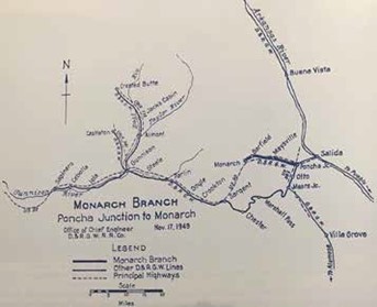
The importance of the operations can be noted in the six day schedule with the light schedule on Tuesday/Thursday/Saturday and basically a double schedule on Monday/Wednesday/Friday. It is important to note that this was a narrow gauge line for most of its life and the loads delivered to Salida needed to be transferred to standard gauge equipment for the remaining journey. The traffic on the line was broken into two or more parts to allow for the length of the switchback tails and the length of the available sidings. The two engine trains were more efficient on the line as the split trains could be handled by separate power without backtracking. The single engine trains were required to deliver the ten cars and return to Garfield to pick up the next ten cars for the tipple.

Salida/Maysville Operations
- First Crew Call: 4:00 am
- Report to Work: 5:30 am
- Train to Monarch
- M-W-F: 2 Engines / 56 Empties / Caboose
- T-Th-Sat: 1 Engine / 28 Empties / Caboose
- Maysville: Stage Half of the Train
- One half continued to Monarch
- Road / Helper return with 10 to 14 loads
- Return to Monarch with 2nd Half of Empties
- Return to Maysville with another 10 to 14 loads each
- Return to Salida around 3:00 to 4:00 pm
- M-W-F: 2 Engines / 40 to 48 Loads / Caboose
- T-Th-Sat: 1 Engine / 20 to 24 Loads / Caboose
- Second Crew Call: 1:30 pm
- Report to Work: 3:00 pm
- Train to Monarch
- 1 Engine / 28 Empties / Caboose
- Return to Salida around 1:00 to 2:00 am
- 1 Engine / 20 to 24 Loads / Caboose
It should be noted that the train lengths were longer on the inbound side than the outbound side, meaning that there were additional moves beyond the noted schedule moves to keep the sidings available for the inbound traffic. The characteristics of this branch were the restrictive lengths of the sidings and the switchback track which kept the train lengths short, and the movements carefully orchestrated. These operational difficulties add appeal to modeling the branch.

Garfield Operations Arrival
- Maximum of 14 Gons + Engine + Caboose fit on upper tail of Switchback
- M-W-F: 2 Engines / 28 Empties / Caboosse
- Train split in half
- Road Engine take first 14 cars up switchback
- Helper would take rear 14 cars up switchback
- 28 Car Trains had 1 Engine / 28 Empties / Caboose
- 14 Cars left at Maysville
- Road Engine take first 14 cars up switchback
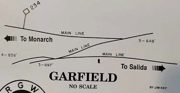
As the map notes the lengths of the switchback tails are 697 feet and 648 feet. The severely restricts the length of trains to operate through these areas. It is important to remember that while this is noted as a main line, the reality is that this branch is just that, a branch line with limited traffic.
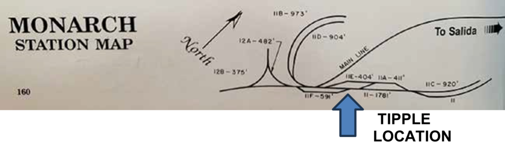
This map shows the trackwork complex at the termination of the branch. To the far right are two empties’ tracks where the empty hoppers are stored to be gravity fed to the tipple location. After loading, the cars continue to be gravity fed to two long curved tracks, noted 11B-973’ and 11D-904’, where the engines retrieved the loads. The power was able to pull the loads up the track to continue back on the main line to Salida. The wye allows the engines to be turned to manage the loads. The wye at Monarch yielded a tender step for Gary Myers as it was used to help locate the tracks after the line was abandoned and salvaged.
Monarch Operations
- M-W-F: 2 Engines / 28 Empties / Caboose
- Road Engine shoves empties up gravity tracks
- Turn Engines on Wye
- Road Engine pulls out 20 to 24 loads from load tracks
- Helper runs light ahead to Garfield Upper Switchback
- 1 Engine / 28 Car Train / Caboose
- Road Engine shoves empties up gravity tracks
- Turn Engine on Wye
- Road Engine pulls out 10 to 12 loads from load tracks
The Garfield map above can be used to help understand the departure operations at Garfield or more specifically the switchback moves needed to continue back to Salida.
Garfield Operations Departure
- Maximum of 14 Gons + Engine + Caboose fit on upper tail of Switchback
- M-W-F: 2 Engines / 28 Empties / Caboose
- Road Engine cuts 10 cars from train, proceeds down switchback
- Helper backs on upper tail of switchback and brings rear down to siding
- Helper cuts off train, runs light to Maysville
- Road Engine connects both halves of train runs to Maysville
- 1 Engine / 28 Empties / Caboose
- Road Engine cuts 10 cars from train, proceeds down switchback to siding
- Road Engine returns up switchback to retrieve rear of train
- Road Engine backs brings down rear of train to siding
- Road Engine connects both halves of train, runs to Maysville
As this line was operated under steam power for most of its life, a couple of other features are worth noting. There was a water tank located at Silver Creek, MP 229.63, which was later changed to a cistern/standpipe.
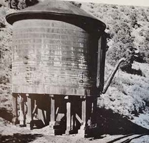
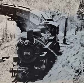
The Garfield Water Column was gravity fed from a concrete cistern above the grade, located above the Monarch Lodge.

After the return to Salida, the narrow gauge gondolas needed to be transferred to standard gauge cars to continue on to Pueblo. This was early on a very labor intensive hand transfer, but the D&RGW constructed a barrel transfer at Salida to unload the gondolas. This was as advertised, a rotating table which rolled the narrow gauge gondolas over the standard gauge car/tracks below to quickly transfer the load. This worked well to move the product, either coal, limestone, or other ore. The problem was that the materials which were sized before the barrel were resized in the unloading operation. Ultimately, the tracks and gondolas below the barrel were replaced by a fixed gondola modified to discharge the materials onto a conveyor to a re-screening process. This satisfied the customers and allowed the narrow/standard gauge transfer to continue on the branch lines.
Ultimately in 1956 D&RGW ended the steam operations. The Monarch branch was converted to standard gauge and dieselized. This conversion was accomplished in a month. This eliminated the material transfer at Salida and allowed the loaded material to be moved to the destination in the loaded cars. This brought more color to the operations to better match the scenery, particularly in the fall.
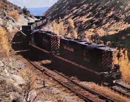
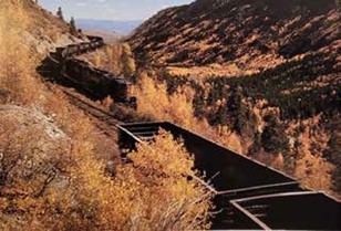
One of the frustrating aspects of reviewing the photos and mapping of the area is the fact that the maps are generally oriented with north being towards the top of the sheet while the photos are taken from the north facing south. This makes the current orienteering difficult as the tracks were removed in the 1980’s.
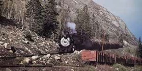

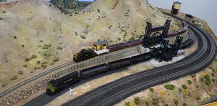
August Clinic – August 27, 2023
The Infamous Front Range Division Picnic
As it was the month of August, it was again time to gather away from the Colorado Railroad Museum and hold the “Clinic” at another venue. This year the Scenic Line Modelers, Inc. (SLMI) opened their layout for tours, and Lockheed Martin allowed us to use the picnic pavilion for our picnic. We had an excellent turnout, and a great number of picnic foods and desserts to go with the annual fried chicken and sodas. The Division wants to thank Superintendent Rich for the chicken and Paul Brennecke for the sodas. We wish to further thank all who brought the picnic foods and desserts for all to enjoy. This year we had the trifecta of good fortune; good weather, good food, and great conversation.
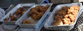

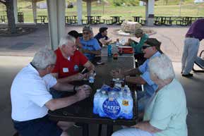
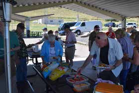
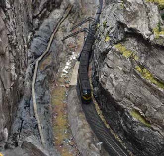
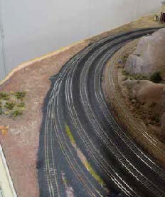

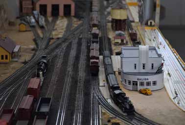
July Clinic – July 17, 2023
The New Mexico Division – Designing a Railroad for Operations Based on the Prototype
In his clinic Bob will explain why he selected the Glorieta Pass area of New Mexico to model, which prototype elements he elected to include, and why; and the compromises he chose to live with as he developed his track plan. Along the way he will discuss some general principles for designing a model railroad, why it is sometimes necessary to deviate from the prototype: and how the ultimate objective should be to develop a railroad that meets the builder’s goals and desires. Attendees will receive a copy of Bob’s somewhat “tongue in cheek” handout titled, “Bob Foltz’s Axioms, Rules and Guidelines for Layout Planning and Operations”.
Bob Foltz Biography
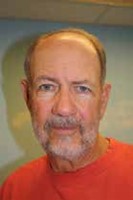
Bob Foltz retired from the Army as a Lieutenant Colonel in 1991. As an Aviation Officer he was dual rated on both helicopters and airplanes, accumulating a little over 4000 flight hours. He was also a Latin America Foreign Area Officer and worked extensively throughout the region. He retired from his second career as the CEO of a nonprofit agency in 2009.
Bob earned his BA from LaSalle University in history in 1971 and his MA in International Relations and Latin American Studies from American University in 1982. He is also a graduate of the Defense Language Institute in Spanish.
Bob and his wife, Linda, are very active in the Alpine Mountain Region of the Porsche Club of America and is on his third “final and last” Boxster S. In addition to model railroading, he enjoys skiing, studying Spanish and reading. Bob has been modeling the Santa Fe Railroad since 1975. He is the author of over twenty-eight articles in the model railroad press and has presented numerous clinics at the Division, Region, and National level. His current layout, the “New Mexico Division,” was featured in the June 2011 Model Railroader and has been operating his current railroad since February 2002.
Bob Foltz joined us to give his clinic on his New Mexico Division of the Santa Fe Railroad. The clinic focused on the means and methods he used in designing this version of his model railroad. Bob started building model railroads when he was 11 years old. As time went on, life interrupted his modeling giving him pauses and breaks in the pursuit of railroad modeling. He identified five areas to include in the clinic. First one needs to decide on your modeling preferences. You need to consider a prototype to model or to freelance a railroad. Select the features that you would like to include. Delve into the compromises for the layout and modeling. This is mostly size, budget, and time constraints. In all probability, operations should be considered in all the areas. How would you operate the railroad? What size crew is needed and available to make the operations happen?
This clinic and the ideas that will be discussed are a result of a number of years of modeling the Santa Fe Railroad. He is the author of over 28 published articles on model railroading. The latest model, the New Mexico Division is his second operation oriented pike and has been in operation since 2002.
The first operations based layout began operating in 1991. This layout was focused on the Raton Pass area. This layout was featured on four magazine covers. The layout did have a few flaws and corrections to these areas which generated more magazine articles. This led to his belief he had made all the mistakes that can be made. He has determined that he has learned from some of the mistakes and is somewhat older and a bit wiser.
As luck would have it, he began the New Mexico Division in 1998. They had found a new basement layout space with an acceptable house above. This timeframe coincided with the emergence of DCC, code 83 track components becoming available, well detailed plastic steam engines becoming available, and laser cut kits of Santa Fe structures becoming available. All of these elements would lead to the development and construction of the new layout.
In the spirit of John Armstrong’s “Givens and Druthers”, Bob compiled a general listing to guide his processes. His druthers included his favorite prototype, Santa Fe, the locale, style of operation, equipment desired, and the era of the railroad. His parameters were the available space, financial resources, and the time to devote to the railroad. The critical elements were expanded to include:
- A helper district
- Single track mainline using Time Table & Train Order (TT&TO)
- Some local switching
- Rugged Western terrain – that is Santa Fe country
- Santa Fe Warbonnets and streamliners
- Big steam locomotives
- First generation diesels in zebra stripes
- Lots of Santa Fe F units
To locate the “rugged western terrain”, he reviewed the Santa Fe system map to find the areas he wished to model. Mountainair / Abo Canyon had rugged terrain. Raton Pass had terrain and the desired operational difficulties, but it has been the subject of many model railroads. The Williams / Seligman area was considered but was quite remote with limited switching opportunities. Cajon Pass was reviewed but again this area has been the subject many model railroads. The Tehachapi Loop area was an interesting location, but again the subject of many model railroads. And then Glorieta Pass was reviewed, and it had a number of positive attributes particularly in 1951. This was a helper district for the high railroad grades through the Pass. This was a single track mainline area under TT/TO control. With the number of Santa Fe passenger trains passing through the district and some local switching, it seemed to be a great modeling possibility. The 1951 time frame gave rise to Santa Fe steam and first-generation diesels in use. Finally, some bonus features were identified; it was a Santa Fe subdivision, it serviced the Madrid coal mining district, Absolute Permissive Block (APB) signaling was used over the district, and finally, nobody was modeling it. This work gave rise to a two part article in the Railroad Model Craftsman on designing the railroad.
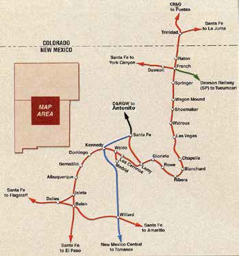
This map shows the Glorieta Pass area and the ATSF system. Further research was carried out utilizing the Santa Fe track chart from the Santa Fe Railway Historical & Modeling Society, and the Car Location Inventory Control from the Santa Fe Engineering Services. The track charts show the track arrangements in the modeling target towns including Las Vegas and Lamy.
Track planning for the model railroad was an involved process. The first step was to make an accurate drawing of the available space with obstructions, support columns, utility & mechanical systems access. One needs to draw in the benchwork or more importantly the aisle plan. The first items added to the plan were the yard locations. Then, he added in the track wyes, peninsulas, and blobs. The aisle locations and widths in the plan were annotated. Finally, the staging area was added to the plan. In this instance, and for this railroad, the plan was just a road map not a rigid plan. The critical operational areas were added first, Las Vegas, Glorieta, and Lamy. The location of the key scenic features were determined, and other town sites were added to the plan. These other town sites were combinations of actual towns to add industries and sidings to the area. The areas were connected together with the mainline. Compromises were made in the plan to add operational activities throughout. The Dawson Mining District ties into the Santa Fe Railroad at Springer instead of French, the Southern Pacific rail line to Tucumcari is an interchange. The narrow gauge trackage in Santa Fe was removed by 1941, but it lives on with this track plan. The towns of Waldo and Los Cerrillos were combined into one location. (Note: Waldo has been found!) The Madrid mining district was reduced to a staging location.
The planning and track plan were topics of a couple more railroad magazine articles. The final track plan is shown below.
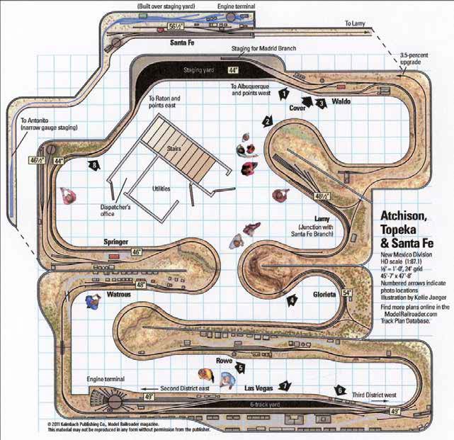
Note the prominent location of Glorieta and the pass on the layout. The narrow gauge Denver and Rio Grande Western is located around Santa Fe in the upper part of the diagram. The staging located below Santa Fe represents Raton to the left and Albuquerque to the right. Additional staging was planned to the left of Las Vegas, but the area was too narrow for the tracks desired. That is the reason that the 14 track double-ended staging was located under Santa Fe.
A photo tour of the layout starting in Raton proceeding to Springer. The depot at Springer is a focal point of the location. Several local industries are rail served at the Springer location.
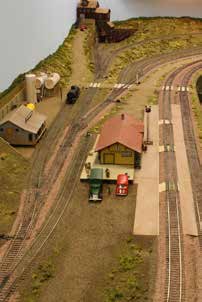
Semaphore signals are still in use on this line with a set near Raton and as one departs Springer. The line passes through Shoemaker Canyon on the way to Waterous; passing the Canyon Palisade rock formations and over the Mora River Bridge. At the current time the depot is gone from Waterous, and Railroad Avenue is a mere shadow of its former self.

For the model railroad, Waterous is still a thriving community with the depot and freight house bustling with activity. Highway 94 Overpass just outside Waterous is helpful as a scenery break moving to the Pecos Arroyo with a through truss bridge spanning the drainage.
The next stop is Las Vegas which is a highlight of the layout. Las Vegas had a major Santa Fe depot and a Harvey House hotel and restaurant, the Castañeda Hotel. These structures are prominent in the town. The yard is a major modeling element with the trackwork modified for smooth operation. The rail area includes a turntable and a roundhouse with engine servicing facilities. The service facilities include a waycar and caboose track. The town has a freight house and office facilities.
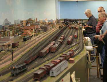
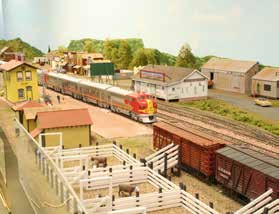
The next location is Rowe. Presently, there is no town left. At the model era, the town was thriving with a livestock loading facility and freight house. Leaving Rowe, the train passes over the Gallinas River.
This brings us to the signature area of the railroad, Glorieta Pass. Glorieta was located near the Pass which was a station with a freight house to service local residents.

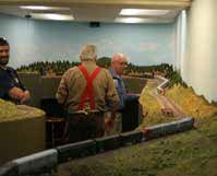
This photo shows the Pass during an operating session. The pass has a ruling grade of 3.095% eastbound and 1.71% westbound. This gives rise to the need for helper service to get both freight and passenger trains over the pass. The station is in the foreground of the photo.
The trains continue on through Apache Canyon. The canyon is the location of the Spider Bridge. Bob Foltz’s rendition of the bridge is a single spider leg when the prototype uses a double spider leg, one to each side of the track. This is the division point for the Santa Fe Branch through a wye and into Lamy with a small yard.
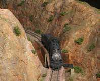
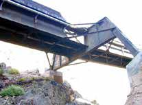
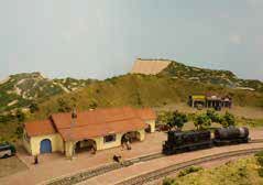
The Lamy depot is the centerpiece of the town. The town has shrunk to a few buildings. The tracks continue on to Waldo and the start of the Madrid Branch which is represented by a small staging area near the major staging yard. The mainline terminates in the staging yard representing Albuquerque and points west. The Santa Fe Branch continues up to an upper level where the Denver and Rio Grande narrow gauge tracks coexist with the standard gauge standard gauge tracks of the Santa Fe. This gives cause for dual gauge tracks in a few areas of the yard. Of note is the operating sessions have a good deal of competition for the narrow gauge operating area. The difference in size makes this area an interesting comparision in operations.
We backtracked a little on the layout to examine towns that were combined. Los Cerrillos / Waldo were combined on the layout into one location named Waldo. Los Cerrillos is a historic mining and ranching center. The area has a geological item of interest called the Devil’s Throne. Waldo has an interesting industry associated with the area. This would be the coke ovens lining the small bluff outside of town. Reminents of these are still visible but the works have largely eroded away.
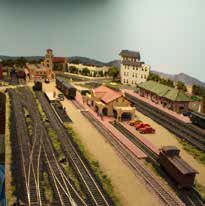
Santa Fe was the capital of New Mexico that was bypassed by the mainline Santa Fe. The two depots, the Santa Fe and Denver & Rio Grande Western, are still in use in Santa Fe. The Santa Fe depot functions as the station for the Rail Runner commuter line. The area on the layout is well detailed with the signature structures in evidence. The narrow gauge rails are to the right of the photo. The narrow gauge line extends to Espanola with a livestock corral. Its makes its way to Embudo with a mine. The line ends at a sceniced open staging representing the line west to Antonio and Chama.
The Madrid District provided coal for Santa Fe. This was a company town that morphed into an arts and crafts mecca.
Operations on the New Mexico Branch of the AT&SF was the goal of the planning and construction. The trains are controlled by timetable, train orders, and the rule book. Communications to the trains and railroad are handled through a phone system. This system is not complex but provides communications with the dispatcher. Train order boards are indicated by semaphores at the station locations. This is fed back through lighted panels on the fascia. Absolute Permissive Block signals are in place along the line. Car forwarding is by means of car cards with four sided waybills. The key to a good session is the dispatcher.
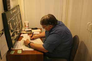
The Front Range Division thanks Bob Foltz for his great clinic on the New Mexico Division.
Bob Foltz’s Axioms, Rules, and Guidelines for Layout Planning and Operations
- How much staging Do You Need? Figure out what you think you need, double it, and add one you’ll still wish you had more.
- You’ll never regret putting in wider aisles, but you will always lament aisles that are too narrow.
- Use the widest radius curves you can and you’ll end up wishing you had enough room to have made them even broader.
- You’ll never regret using a longer turnout – you’ll always regret using that short turnout to squeeze in one more track.
- No matter how much you test your railroad, you’ll never be able to put the pressure on the physical layout that the first operating session will.
- No matter how well you plan, you won’t know what works until you subject it to the pressure of an operating session.
- No matter how much you “war game” the possible ways to work a train or yard, your crew will find ways to do it that are beyond your dreams.
- Begin operating as soon as possible, and definitely before the scenery goes in. Your crew will come up with all kinds of track change suggestions to improve the work and traffic flow. It is much easier to make these changes before the scenery goes in.
- Politely consider all change recommendations made by your crew, but feel free to accept or reject them. After all, it is your railroad, and the only person you have to please is yourself.
- No matter how much time you devote to writing clear operating instructions, your crew will misinterpret them – or simply not read them at all.
- No matter how often you cover something in the pre-session briefing, at least one of your crew will ask you about that very same subject later in the session as if it had never been discussed before.
- Car’s derail, couplers won’t couple, and engines need an occasional nudge during an op session. If you don’t want your equipment handled, then don’t host op sessions.
- Equipment that gets handled will sustain minor damage. On rare occasions, a model might even hit the floor. Be prepared to accept this and make repairs, or don’t host op sessions.
- You and your crew will find grab irons, brake wheels, and other miscellaneous pieces along the right of way with no idea where they came from. Keep a small container on the workbench for these odd parts. You’ll eventually find cars that need these pieces.
- Even if you developed a perfect Bad Order reporting system, at least one crew member will come up during the session and tell you that “the coupler on the B end of boxcar 12345 is low” – and then never write it up.
- Keep a note pad handy to write down that “the coupler on the B end of boxcar 12345 is low” or any other deficiencies that get reported or that you notice. I guarantee that you’ll never remember these the next morning otherwise.
- Correct all the items on your maintenance list. Bad order reports and other noted deficiencies before your next session – You owe that to your crew.
- A modest sized railroad that is well done and relatively complete will probably provide more satisfaction than a massive dream railroad that never gets beyond the plywood stage.
- Spending extra time to lay good track will never be wasted. It takes more time to correct problems than it does to do it right the first time.
- Most model railroaders’ own way more cars than they need. Don’t overcrowd your railroad with cars. So, take the excess off the railroad.
- If a yard is half full, it is Too Full!
- No matter how long you make your sidings, they will end up being one car too short. You’ll find this out during your first operating session.
- Inevitably, more cars than you have room for, or the wrong type of cars will show up at an industry. You’ll also find this out at your first operating session.
- Operators are very creative in the ability to create new ways to screw up. No matter how simple the rules are, somebody will ignore them.
- We all have a vision of what we are trying to achieve with our layout. We do not all share the same vision; therefore, operators who do not share your vision will find other railroads to operate on.
- Don’t take it personally if someone comes to a session or two and never comes back. Your vision, operating scheme, or simply operations in general may just not be his or her “cup of tea.”
- Nothing equals the satisfaction of watching your railroad “come alive” during your first operating session!
- Don’t take yourself or your railroad too seriously. Remember, this is supposed to be fun!
June Clinic – June 19, 2023
Prototype Railroad Experiences & Modeling Perspectives
Have you ever been trackside; wondering why a particular freight car was in the train or why the car was spotted on a customer siding; and wondered where it came from and what it contained? In this session, we’ll dive into the “why” behind railroad traffic and industries, and how it relates to what we see trackside, with implications for modeling and operations.
Kevin Ruble Biography
Kevin Ruble is a fourth-generation rail professional, having started his railroad career immediately after college as a management trainee, and subsequently Assistant Manager – Car Service for the Missouri-Kansas-Texas Railroad (better known as the Katy) in Denison and Dallas, Texas. After graduate school, Kevin served as a strategic consultant for over 85 short line rail transactions over the span of 25 years, culminating in the acquisition of a 126-mile CSX branch line in Michigan, from which Marquette Rail was formed in 2005. Kevin was Marquette’s Founder, Managing Member and CEO prior to the railroad being sold to RailAmerica (and ultimately Genesee & Wyoming) in 2012. A few years after moving to Colorado, he acquired the remaining assets of Caboose Hobbies in 2016, after that iconic store closed, and moved the store to Lakewood, where it operated until closing with the COVID pandemic at the end of 2020, but let’s not dwell on that sad story.
Railroad Industries and Freight Traffic
The “WHY” behind Prototype Railroad Operating
Kevin Ruble brought us a presentation on a lifetime of railroading knowledge. There is a spectrum of model railroading which categorizes the model railroad as to its broad function. There are those who model based on the toy trains of youth. They enjoy the continuous operating, and the wealth of accessories that mimic railroad related industries. There are modelers who prefer “rail fanning” layouts with interesting scenery that is tied to the specific modelers locale and chosen railroad. The operators are the ones with the most to gain from this information as they engage in operating the railroad. They get the most enjoyment out of building trains and delivering and receiving car loads to industries along the route. To add realism to the operating scheme, it is good to know what type of goods or materials are delivered in the era specific model cars and what routing would be optimal for the railroad. Kevin’s interests in the prototype world were business development and developing handling schemes for those types of businesses.
There are many model railroading corollaries, but operationally – never say never or never say always. Put nicely, there are always situations and practices that are outliers. As with any large and complex industry, there are a number of different ways to approach or complete an operation. The necessary part of railroading is to move freight, people, or whatever else from point A to point B safely. Model railroading Rule Number 1 – Whose railroad is it?
It is important to remember that prototype railroads are transportation businesses. This brings a number of requirements including the fact the railroads are common carriers. These are required to accept freight and move the commodities over given routes for established rates. The railroad traffic is further divided into line haul or switch traffic. Under line haul traffic, your railroad is in your routing and rate structure. Line haul traffic is in the reported figures for loaded cars, but not as empty cars. This means it is possible the railroad handles twice as many cars as indicated in the reported figures. For switch traffic, the railroad only earns a set fee for delivery or pick up of a car to deliver to the line haul carrier. This sets up a line haul carrier as the more lucrative business. There are several categories of line haul traffic:
- Originated traffic – shipper is on your railroad.
- Terminated traffic – receiver is on your railroad.
- Local traffic – both shipper and receiver are on your railroad.
- Overhead or bridge traffic – neither shipper or receiver are on your railroad. The car is being handled by other railroads as incoming or outgoing loads.
To maximize income to your railroad, it is best to be the originating railroad. That means you set the route, rate for the shipment, and collect all the freight charges due for the shipment. Local traffic is common on large Class One railroads as their rail lines are more extensive and interconnect business centers. This type of traffic generates more revenue per ton/mile than other categories. Class Two and Three railroads seldom have local traffic as the line reach is not extensive enough to capture both the originator and termination locations.

A prototypical example of this is pulpwood loads to a paper mill. A railcar can accept 2½ to 3 truck loads of pulpwood and move that load at $550 to $600 per railcar. The truckers could not compete with that rate as their haul cost would be $250 per truckload. This is an example of a commodity suited for rail transport.
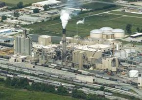
Reciprocal Switching is more typical in large terminal areas served by a number of railroads. Mutual access is granted by the industry to local line haul railroads. An example is the former A.E. Staley, now Tate and Lyle, plant on the Nickel Plate Railroad, but the plant was open to reciprocal switching, so not only could the Nickel Plate quote line haul rates, but the Monon, Wabash, and New York Central could quote line haul rates, if the plant was located on their roads. The Nickel Plate would handle all the switching at the plant for an established switch fee.
Switching and Terminal Railroads serve a variety of customers connected by their trackage and are neutral terminal facilities. These are most often found in major cities. Examples include:
- Belt Railway of Chicago
- Indiana Harbor Belt
- Kentucky and Indiana Terminal
- Houston Belt and Terminal
- Kansas City Terminal
These railroads handle cars between line haul railroads and each other, or on-line industries for a switch fee. These railroads are not typically part of the line haul routing and rates. Within this structure, the industries on the switching and terminal lines are effectively on-line customers of the line haul carriers. These switching and terminal lines are usually jointly owned by some or all of the line haul roads they serve.
The determinants of “WHY” for rail traffic flows. Three, really four, primary factors determine why you would see a carload of a certain commodity at a given location:
- Economic considerations
- Geographical factors
- Business relationships
- Other stuff
Economic considerations include freight rates which are a function of the value of the commodity and the distance of the haul. In addition, the rates do include a valuation of the risk of the haul. Chlorine costs more to haul than corn syrup. The go/no go on the consideration is whether the railroad can make any profit on the freight. Non-compensatory moves are not a requirement of being a common carrier. Typical rail-hauled commodities are codified by the Standard Transportation Commodity Code (STCC) with a standardized name and a seven digit code. Those commodities currently being hauled by the nation’s railroads include:
- STCC 01 – Farm products
- STCC 08 – Forest products
- STCC 09 – Fresh fish / marine products
- STCC 10 – Metallic ores
- STCC 11 – Coal
- STCC 13 – Petroleum and products
- STCC 14 – Non-metallic minerals
- STCC 19 – Ordnance or accessories
- STCC 20 – Food products
- STCC 21 – Tobacco products
- STCC 22 – Textiile mill products
- STCC 23 – Apparel
- STCC 24 – Lumber / wood products
- STCC 25 – Furniture or fixtures
- STCC 26 – Pulp, paper, or allied products
- STCC 27 – Printed matter
- STCC 28 – Chemicals or allied products
- STCC 29 – Petroleum or coal products
- STCC 30 – Rubber or miscellaneous plastics
- STCC 31 – Leather and leather products
- STCC 32 – Clay, concrete, glass, stone
- STCC 33 – Primary metal products
- STCC 34 – Fabricated metal products
- STCC 35 – Machinery excluded electrical
- STCC 36 – Electrical equipment
- STCC 37 – Transportation equipment
- STCC 38 – Instruments, clocks
- STCC 39 – Miscellaneous manufactured products
- STCC 40 – Waste or scrap materials
- STCC 41 – Miscellaneous freight shipments
- STCC 42 – Shipping devices, empty
- STCC 43 – Mail, express traffic
- STCC 44 – Freight forwarder traffic
- STCC 45 – Shipper association traffic
- STCC 46 – Miscellaneous mixed shipments
- STCC 47 – Small packaged freight
- STCC 48 – Hazardous waste
- STCC 49 – Hazardous materials
- STCC 50 – Bulk boxcar shipments
The STCC shown above are the first two-digits of the complete seven-digit code. The next three-digits further categorize the producing industry, and the last two-digits give the specific quantity identification. There are over 10,000 codes in the index.
Note that these are the current commodity categories transported by rail. For your railroad’s era and location, the list might be very different.
Geographical considerations for rail traffic include transiting the central U.S. Those movements go through Chicago, Saint Louis, or other central U.S. gateways from the west to the east or east to the west add cost to the freight rates. This is the nature of the railroad’s geographic reach. The eastern railroads were well developed prior to the development of western transportation. Interchange between railroads was and continues to be at a higher cost. Also, lower value fungible commodities don’t move beyond alternative origins of the same commodity. An example would be that aggregate, crushed stone, would not be railed two hundred miles, if a similar source of material is found within one hundred miles of the destination.
Business relationships come into play in routing and selection of rail way points. An example of this is the Roscoe, Snyder & Pacific Railway Company. This railway had a nationwide network of sales representatives which touted the fact the railroad could be a bridge route between the Santa Fe and Texas & Pacific railroads between Snyder and Roscoe, Texas, in spite of the direct connection and interchange at Sweetwater located 8 miles east of Roscoe. The railroad was 31 miles in length. For most of the traffic, the originating rail line will set the rates, determine the routing, and collect the revenue. The routing is an important component of this relationship because the originating line will keep the shipment on its rails for the greatest distance. The other stuff involves the business of controlling the rail line’s destiny. Being an originating carrier gives the company an advantage in establishing rates, determining routing to other carriers, and being smart on keeping your company at the forefront of the shippers and receiver’s mind.
There is a relationship between rates and the commodities as higher value materials will travel longer distances than those of lower values. Rarely do commodities travel longer distances to where similar materials are available at a shorter haul. The exceptions would be in times of shortages, longer hauls may be acceptable to supply the demand. Also, in longer hauls the number of railroads affects the rate and the viability of the shipment. Continuing on, we stepped through some examples of relative value and length of haul. Which will travel at a higher rate, a hopper of coal or a tri-level auto rack of new BMW cars? The auto rack of course is a better source of revenue for the railroad. How about a container load of new TV’s or a boxcar load of scrap paper? The container load of TV’s will travel farther on the rails. How about a tank car of chlorine or a hopper load of crushed limestone? The chlorine has a much higher value and will travel farther on the rails. And finally, how about a covered hopper car of corn or plastic pellets? The plastic pellets will travel farther on the rails due to its greater value. Kevin continued on with examples from his favorite railroad, the Monon Railroad. This railroad is unique in it was the first Class One railroad to fully convert to diesel power, and zero miles of double track. Based on this, one can construct a model railroad with first generation diesel power on a switching puzzle. This railroad served seven colleges and universities along its line, including Purdue University, Wabash College, DePauw University, Indiana University, Butler University, St. Joseph’s College, and West Baden Northwood Institute / College. So one could claim that it is an educated line. The line was all in Indiana and connnected to Chicago, Michigan City, and Louisville by use of Switching Railroads in the area.
One of the industries served by the Monon was the Davidson Chemical Division of W.R. Grace located in New Albany, Indiana. It received loads of the raw materials from U.S. and Canadian locations. The potash came in railroad owned covered hoppers (CP, ATSF, D&RGW) or shipper leased covered hoppers, and returned empty. The phosphate came in via railroad owned covered hoppers (ACL, SAL) or shipper leased covered hoppers, and again returned empty. Nitogen and ammonia was shipped in private tank cars from the Chicago area, the Northeastern U.S. , and Texas and Louisiana Gulf coast; and returned empty. The outbound product was shipped in railroad owned covered hoppers, boxcars, or shipper-leased covered hoppers and tank cars. With this variety of inbound and outbound cars, this was an active place.
Another New Albany industry is Pillsbury Mills which produced refrigerated dough. You should be thinking the Pillsbury Doughboy. This refrigerated dough process was invented by Mr. Lively Willoughby, and is used for a number of bakery products. Inbound flour comes in covered hoppers from Springfield, Illinois, and other points. Inbound plastic resins for the little plastic cups of icing, arrive from the Northeast and Gulf Coast. Inbound pulpboard comes in from the Southeast for packaging. Finally, the refrigerated dough products are shipped via trucks. There are pooled and assigned cars that are dedicated for specific loading. These assigned cars can be marked “Appliance Loading only. When empty return to General Electric, Appliance Park, KY”, or “Grain Loading only”, “When empty return agent MON, Bainbridge, IN”. Basically these cars are captive to a single shipper bound to a single or multiple receivers. Pool cars on the other hand are assigned to a specific major industry and are cars of differing railroads based on the proportion of traffic in that industry. Autoracks are a common example of this type of car. Another example is the Rio Grande cookie boxcars. These were specially modified boxcars to handle shipments from the Bowman Biscuit company bakery located just west of the D&RGW’s north yard in Denver. These were largely single car shipments to distribution centers throughout the West.
The Monon traffic for 1970 is shown on the chart below.

The most important item to note is that the Monon originated 30% of its traffic. Those loads were where the railroad could set the rates and determine some routing. The terminated and forwarded loads amount to 70% of the business. This line item is a little confusing as the terminated and forwarded loads are combined, so it is difficult to analyze the makeup of this traffic. The average cars per train is important because of operating rules; a 69 car train required a 6th crew member. The balance of loaded cars to empties is interesting as it shows a good utilization of rail cars on the line.
The next chart shows the distribution of commodities traveling on the Monon in 1970. The largest component shown is the rather nebulious “All Other Commodities” at 37%. This gets the chart to 100%, but doesn’t really give the ownership a target for increasing revenues and focused marketing. The next highest traffic in tons is coal at 19%. Industrial chemicals originated in Louisville at 6%. Abrasives, asbestos, etc. follows with 6% of the tonnage. Fertilizers at 4% are largely from the Davidson Chemical noted above. The corn percentage at 3% is interesting as within Indiana a great deal of corn is grown. The thought was that the L&N railroad captured a lot of this business in the southern part of the state.

In order for the modeler to get a snapshot of the train makeup, one should review the consist or manifest documents for the railroad. This shows what rail cars and their owners were used on the specific trains. Using this as a guide, the modeler can make up realistic model trains for the layout.
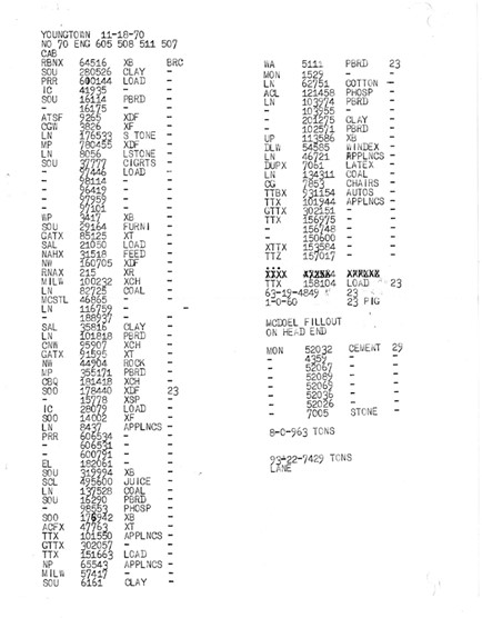
This document is the consist of Monon Number 70 at the Kentucky & Indiana Terminal, Youngstown Yard for November 18, 1970. The train was heading from Louisville to Chicago with 62 loads and 19 empties for a total of 81 cars. This shows 36 cars for the Belt Railway of Chicago and the remaining 45 for the South Hammond Yard. Those South Hammond cars will go to other connections through Chicago. The train has many cars of overhead traffic which is quite sketchy. The amount of this traffic meant eventually the Monon would need to find a merger partner in either the L&N or Southern railroads. The largest number of carloads are appliances from General Electric. The plant in Louisville is sighted on 750 acres with its own zipcode and city services.

This consist is the document for Monon train number 72 again at the K&IT Youngtown Yard from October 23, 1970. 71 loads and 21 empties for a total train of 92 cars. The majority of the cars on this train are to go to the Belt Railway of Chicago. This is one of the sequence of events that led L&N Railroad to buy the Monon about a year later. This had the consequence of shutting Southern out of Chicago. The majority of the cars are appliance loads on a wide variety of railroad cars in pool service for GE. The next largest group of cars are loaded with clay. Of note is an Lackawanna car in the consist of Windex, some 7 years after the Erie Lackawanna merger.

This consist of Monon Number 71 at South Hammond in October 29, 1964. This is a smaller train with 37 loads and 28 empties for a total of 65 cars. 54 cars are headed to Louisville with 8 going to Bloomington and 3 set out for New Albany. The mix of cars and railroads shows the diversity of the bridge traffic. This train will pick up 5 cars of RCA cabinets from Monticello near Monon bound for Bloomington. Interestingly, Number 71 will pick up 11 empty covered hoppers from the EJ&E to take back to Mitchell, Indiana for cement loading. This includes 3 FEC cars probably on lease until the Monon covered hoppers were delivered.
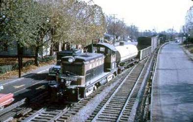
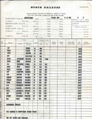
This consist is for the New Albany switcher for January 3, 1966. This is the early morning run from the K&IT Youngtown Yard into New Albany to switch local industries and interchange with other railroads. This consist has 20 cars with 15 loads and 5 empties. The five empties include only one Monon road car with the others to be reloaded and moved north. It is generally better to load foreign road cars and moving them off your railroad instead of loading your own cars. This switcher handled the flour cars for Pillsbury set out by trains 73 and 71.
As a summary, cars most likely reloaded toward the home road include:
- General Service Boxcars (unequipped)
- General Service Gondolas (unequipped)
- General Service Flatcars (unequipped)
- Hopper Cars
This follows the reloading of the foreign road cars and move them off the railroad. Hopefully, this will allow the cars to return to their home roads.
Keeping with the recurring theme of the clinics, to move your model railroad along, do some or a lot of research on the prototype. Your research should include:
- Industries and commodities
- Traffic patterns and traffic flows
- Connecting Railroads
- Train operations
- Equipment rosters and assignments
Remember Rule #1 – it’s YOUR railroad! Have fun!
There was further discussion on rates, weighing of cars, and structuring pricing for railroad’s advantage.

May Clinic – May 15, 2023
The Art and Science of Kit Bashing
Due to a scheduling problem, Gerry Glancy presented his clinic on the “Art and Science of Kit Bashing”. This clinic was given at the Rocky Mountain Train Show, and it covers Gerry’s journey of kit bashing structures for his Dueling Gauges Railroad and Navigation Company. As is Gerry’s custom after a short introduction, there is a pre-test on the subject matter, and to conclude, a post-test.
The initial introduction included a definition of a kit bash. Altering one or more commercial kits by adding to or removing from the model, so the appearance of a completed structure is different than the intended manufacturer’s building. The completed structure achieves an important personal goal. In most instances, the kit bashed structure is to resemble a historic building fitted to the available space on the model railroad. The kit bash is to meet the architectural style and mimic the structure to be modeled.
For the modeler, what items can be kit bashed? Those kit bashed items could include structures, bridges, rolling stock, locomotives, and ships. Gerry finds structures the most satisfying kit bash exercises, and his preferred material is styrene.

The pre-test was the Hills Brothers Coffee building in San Francisco. This was an Italian Renaissance style building with arched windows, a clear story above, loading dock for railroad cars, an open tower, exposed fire escape, and an open gridwork sign on the roof. What would be good source kits for the building and elements needed to successfully model such a structure? The building still exists in the city, and it boasts an unusual variegated brick color and pattern for the exterior.
Gerry moved us into the build plan for kit bashing. First things first, research the prototype. Based on the appearance of the structure, and the space available to be allocated to the structure, select the basic building kit(s) and find contributory and donor kits. Based on those selections find additional components to fill in or add to the basic structure to develop the unique building. Further, determine the additional raw materials to supplement or brace up the resulting shell. With the building components in hand, review the foot print of the structure and mock up the building to be certain the size and mass fit into the overall model location. Cut and fit all the parts for the build and pre-paint prior to assembly. There was some discussion on the pre-painting as it does affect the adhesion of the parts. Gerry gets better paint coverage and coverage of the molded details on the kits with the pre-painting. The effort to scrape the paint off mating surfaces helps in the overall fit and finish of the structure. The final step is the assembly of the structure components.
The clinic continued on with a more in depth discussion on the build plan steps. Under the research of the prototype element, it was recommended to complete an internet search for “images of …”, utilizing the resources on HABS/HAER, locating Sanborn maps for the model years, and Google Earth – historical. HABS and HAER are abbreviations for Historical American Buildings Survey and Historical American Engineering Record. These documents are in the Library of Congress and the National Archives. These resources can be used for many substantial structures. The information can include original plans for the building and historical photographs. The example was the Denver, Salt Lake, and Pacific passenger station in Denver. Sandborn maps are useful for orientation of the structures in relation to railways and streets and are year specific. Using the historical Google Earth helps with aerial views giving some context to the adjacent landscape of the selected structure.
Moving on with the process, we need to select index, base model structure, and kits for the structure. Sources include Walther’s Cornerstone kits, DPM (Woodland Scenics) for turn of the century buildings, Faller/Kibri, and Linde. The Faller and Kibri kits need to be Americanized to fit modeling purposes, but they have a number of arched window and door details that fit the kit bash needs.
Additional components include fire escapes, roof details, awnings, and loading docks which can be found from Walthers as stand alone kits or harvested from other kits. The architectural details can be found from Tichy Train Group or Grandt Line (San Juan Models). In most instances, a modeler can find applicable details or similar details to be modified to fit the scale structure. Finally, the modeler should dive into the junk box to find details and parts left from prior kit building/bashing. Additional raw materials may be needed to successfully kit bash the structure. These are styrene sheets, shapes, and strips from Evergreen and Plastruct. These include the pattern sheets for exterior walls. The Plastruct brick pattern sheets in HO scale have bricks too large. Instead the modeler should select the TT scale sheets that have brick pattern better sized for HO scale buildings. In fact, in using any of these patterned sheets, it is a good idea to check the scale to match the selected index kit. The stucco sheet is multi-scaled, so be certain to check each side. The shapes and strips are self explanatory with a wide variety of sizes to each profile.
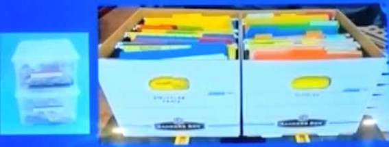
Delving into the construction techniques for kit bashing, the first step is trimming the parts from the sprue. For this, one needs to use a variety of tools depending on the part thickness and the sprue size. To cut the styrene, one can use one of two methods depending on the thickness of the styrene. For styrene of 0.040 inches and less, one may use the score and snap technique. By scoring the surface with a hobby knife or scalpel in multiple passes the piece may be snapped along the scored line. To cut thicker styrene sheet, again score the line with multiple light passes and utilize a razor saw to cut the piece along the line. There is a chance the scoring blade may wander off the desired cut line. Gerry uses a burnishing tool from Tandy Leather Company to smooth over the errant cut to minimize the scored line. There is a selection of glues used for the assembly of the pieces. They include the two Faller solvent glues, one with a longer work time and the other with a very short work period. There are certain applications for CA cement. Walthers Goo is a very good contact cement for anchoring dissimilar materials. Finally, when all else fails, use epoxy to anchor the elements together. Another tip for holding pieces together for review and deciding if the look is there, use rubber cement. This is also helpful in holding parts together to add the final cement. Finally, it is necessary to scrape the paint from the mating surfaces. By painting the parts first, one gets a good coverage of the detail and around openings. It is important to scrape the paint soon after application to make the job easier.
Now the modeler has a pile of kits and bits and pieces to assemble. It is advisable to pre-glue mating parts with dots of cement. This gives a little working time to make final adjustments and to run the bead of final cement. Since the kit bashing generates a number of smaller pieces, it is advisable to buttress the butt joints with scraps of material to stiffen the jointed panel. Gerry was able to bring this all together with examples of his builds. These included the Englewood Santa Fe Station, Denver Union Station, the Embarcadero State Belt Roundhouse, and Embarcadero Piers Number 33 and 35.

The ATSF depot in Englewood was made primarily from the Walthers Mission Style Freight House modified with a short stucco extension and Walthers Mission Style Station for the bay window. A continuous soffit was added to the station with a Spanish tile roof. The corbels supporting the soffit was Tichy parts. To construct the strange font sign for the station, a picture was taken of the actual sign, scaled, printed on paper, and attached to 0.010 styrene sheet which was glued to the wall for support. The structure construction was detailed in the October 2018 issue of Model Railroader.

The State Belt Roundhouse was constructed with the Walthers Three Stall Roundhouse kit bashed to the appearance of the building. There were some problems with the kit as designed. The clearstory in the kit is reversed from the actual structure, and the State Belt has larger windows in general. Finally, the State Line is a concrete building while the Walthers kit is a brick faced structure. The side walls of the kit were shortened by one bay cutting along the pilaster. The windows were enlarged by removing the brick wall sections between the windows. To make up the larger windows, the kit windows were trimmed along the mullion and glued together, resulting in a window to fit the revised brick opening. The rear windows were made up in the same way, but additional donor windows were required. Modifying the wall type meant adding plain thin styrene sheets to the exterior covering most of the brick detail. Some small areas were not covered but with painting and weathering these areas are not noticeable.
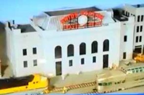
Denver’s Union Station has a place on the layout. To build up this structure in the Beaux Arts style with the arched windows, it was started with the Walthers Bailey Saving and Loan kit. To replicate the mass of the building, it was necessary to utilize two of the Walthers kits. The kits were cut to make up long building faces with shorter wing structures to each side resembling the Union Station footprint. The Mansard roof was made up of styrene pattern sheet material with roof dormers fabricated of styrene. The clock was a wrist watch size mechanism. As luck would have it, after Gerry made up a sign for the building, Miller Engineering came out with a suitable illuminated, animated sign to add to the roof. This construction article can be found in the November 2013 Model Railroader.

The next structure shown was the Embarcadero Piers #33 and #35. These structures have unique architectural elements on the street side, with angled transit sheds behind the bulkhead building, and tracks that move through the bulkhead buildings and onto the piers beyond. In the close enough category, Gerry used two Walthers Pier Terminal Buildings as index kits with an additional kit as a donor kit and yet another as a contributing kit to construct the piers. To construct the face of the bulkhead building, Gerry used the parts from the Pier kits and added a wall from the Bailey’s Saving and Loan to lengthen the structure. The transit shed was lengthened to add the sense of the Pier mass. The tracks needed to be located to enter the central arch of the bulkhead building and exit to the pier adjacent the transit shed. The building footprint was constructed to lay out the track arrangement, and the building pieces to get a proof of concept. At least a 50 foot boxcar needs to fit through the arch and onto the pier beyond. To finish the floor surface and mimic the concrete floor of the pier, Walthers Street Inserts were used. These inserts are fitted to Atlas snap track with radius pieces to match. The snap track is buried by the inserts, so the track joints are not visible. Pier #33 had a clear story skylight structure built up of Tichy windows and styrene shapes and sheet material. Pier #35 has a triple pitched roof that was made up of the kit roof pieces cemented into identical angled pieces and the rear wall of the transit shed was trimmed to match the roof outline. The pier pilings were added to the dock/floor area of the transit shed. These were square styrene pieces roughened to give the appearance of weathered saltwater piles.

Back to the pre-test now being the post test. What was used to construct the Hills Brothers Coffee plant? The index kit for the build was the Walthers Front Street Warehouse. The tower was constructed from Design Preservation Models Modular Wall Panels with the pieces chosen to build up the solid brick tower to open top panel. The tower was topped with a roof made of Plastruct Spanish Tile roofing material. The brick color was the next hurdle with test panels of color to find an acceptable base hue for the brick. The colors found were Tamiya orange with a dark wash and individual brick tones to provide the variation in brick colors. The clear story was fabricated from the kit materials with the added Plastruct roofing material to complete the assembly. The fire escape was from the Walthers Fire Escape kit assembled for a two story application. The loading dock was added along the one long side of the structure. The Hill Brothers sign was constructed using the moveable sign board letters, which for the HO scale building was appropriate. However, the sign letters were not compatible with normal plastic cements. The final solution was to epoxy the letters to the frame so they would stay in place.
There was some discussion on the waybills and routing generated on the State Line.
April Clinic – April 17, 2023
The Evolution of a Railroad, The Education of a Railroader
Poor Pre-Planning Makes for Piss-Poor Performance
Or does it? When Scott started his “Snoqualmie Branch” HO railroad, he wasn’t entirely sure he even wanted to get back into model railroading, so he dipped his toe in slowly. This meant decisions made early in the railroad’s history might not be the same ones he’d make today as “The Snoqualmie Branch” has grown from a one-town switching layout to one which threatens to take over his basement. But those decisions shaped the railroad as it exists today and its future growth.
Scott Ogle Biography

Scott was born in Seattle, Washington, where his love of trains began riding the Great Northern’s Empire Builder and the Northern Pacific’s North Coast Limited to visit grandparents living in Spokane.
The son of a corporate nomad, Scott lived in Seattle, WA.; Phoenix, AZ.; Bellevue, WA.; and Marin County, CA. before being graduated from high school in Honolulu. Several HO railroads were started but left behind in those years. Faced with the choice of Vietnam or college, Scott did his research carefully. He noted, his favorite activity, skiing was not available in either the ‘Nam or Hawaii, but the University of Colorado offered white powder, red tile roofs, and a reputation as a party school. Guessing they probably had classes too, Scott moved to Boulder in 1967 to attend CU, majoring in Broadcasting.
After (miraculously) graduating college, Scott worked his way around various Colorado TV stations, shooting commercials, documentaries, and local news for KKTV, KMGH, KUSA, and KCNC, eventually becoming the Boulder correspondent for NewsCenter4. After a few years, Scott quit local TV to become a freelancer, traveling the world, working for pretty much every broadcast and cable network that identifies itself with 3 or 4 capital letters. Although Scott covered many major news events, he specialized in sports; producing, directing, and shooting everything from World Cup Skiing, through the Olympic Games, Ironman World Championships, Le Tour de France, and 10 years of being the embedded NFL Network crew covering the Denver Broncos including their 2015 and 2016 Super Bowl seasons.
Angela, Scott’s wife of 33 years passed away in 2008. After five years, Scott decided their home in Boulder had too many ghosts to remain living there, and moved to a 55+ community in Broomfield in 2013. The new home came with a huge walkout basement that Scott decided was too nice to just store stuff, and really needed a model railroad to reach its full potential. So, after Scott retired in 2017, he started building “The Snoqualmie Branch”, inspired by a real-life Northern Pacific branch line that went near Scott’s childhood home in Washington State.

Scott Ogle presented his journey from the open basement in his home in Broomfield into “The Snoqualmie Branch” of the Northern Pacific Railroad. This railroad came about after a series of life events landed Mr. Ogle in an over 55 community with a 1880 square foot basement. “You can do a lot of railroading in 1880 square feet.” Scott was born and raised in and around Seattle and memories of his youth included a lot of passenger train trips on the North Coast Limited, the Empire Builder, and other lesser trains connecting the towns in Washington.
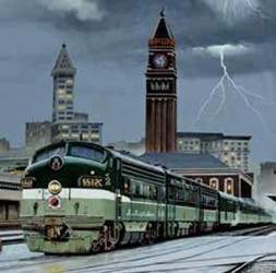
The precursor railroad for his modeling efforts was the Seattle, Lake Shore and Eastern Railway which was first
founded in 1885. The vision of the railroad was to connect Seattle with eastern Washington and northward to Canada linking to the Canadian Pacific. The reality was the line was under-financed for construction and offered great returns to the investors sapping the capital needed to continue viable operations. In more shady dealings, the line was purchased by Northern Pacific Railway without the normal due diligence on the part of the purchaser. This was the start of the Snoqualmie Branch. This rail line started in Seattle and continued north out of the city around Lake Washington to Bothell and Woodinville. The line continued south to Issaquah and turned east to Fall City, Snoqualmie, and ending in Tanner. The line was quite scenic.
Scott constructed an HO scale layout in his youth that had the advantage of fitting under his
twin bed. It was not large enough to handle 85 foot passenger cars. So, the current basement
version has 36 inch minimum radius curves which comfortably accommodate the large
passenger cars.
The route taken by the railroad was not along a river, but rather pushed up mountains and crossed drainages on high trestles. The reason the railroad branch persisted into the 1960’s was the Weyerhaeuser Snoqualmie Mill which produced milled lumber and plywood. The earlier shipments were in 40 foot boxcars which transitioned into 50 foot double door boxcars for more efficient loading of the dimensional lumber. He was trying to get back into model railroading. He was helped along by Caboose Hobbies University series and YouTube sources.
One of the video series he watched was David Popp constructing the Winston Salem Tar Branch which is a small compact railroad plan with a number of industries for switching opportunities. Starting with that plan as a basis, he built a version of that railroad. He was intriqued by the historical research which went into the planning of the Tar Branch and joined the Northern Pacific Railway Historical Association. This gave him access to a large archive of information and photographs to help in planning and setting the stage for his railroad. His planning for the railroad was by hand using pencil and paper rather than track planning software. This has historical advantages and disadvantages. The turnouts are not very accurate, not matching the available commercial units, and the track is denoted by only the centerline which diminishes physical size. The advantage is changing one’s mind is simply a matter of erasing the drawn lines and moving them to your desired geometry.
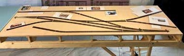
On to construction, he used L-girder construction for his version of the Tar Branch. This gave him the advantage to build upside down. He proceeded to do one-to-one track planning on the benchwork, mocking up not only the trackwork but the buildings. Since this was to be a part of the ultimate railroad, the benchwork was on casters to move it about the space and give it an opportunity to fit in as needed. The legs were fitted with leveling screws to work with the shifting soils. This branch was brought up to ballast, and it was determined he wanted more railroad with a sense of the geography of the Northwest.
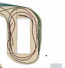
It was determined track planning software did have a purpose for this modeling effort. Scott settled on RailModeller Pro which is a Mac compatible application. This allows the use of modeler specified track elements. His planning lead him to using mountains as scenic blocks to separate the rail lines by the scenery. To make the mountain division of the Snoqualmie Branch, the track planning takes the rails up three levels. This yields a 1.8% grade moving along the track which is close to the 2.1% ruling grade of the prototype rail line. Again, the railroad was constructed on L-girders with cookie cutter track supports. The result was a strong base with probaby too much lumber, but this is sturdy in order to allow for the caster supports and mobility in the space. The whole of the track supports were painted brown because he doesn’t like the pink foam. At this point, the railroad was covered, and the floor joists above were cleaned of the accumulated crud from construction. This was a dirty process, but necessary to keep the model railroad clean.
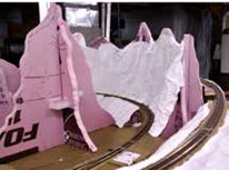
Next came the mountain construction. The trackwork was in place, but no mountains were there to separate the adjacent tracks. Shaper Sheets were introduced in a clinic, and this seemed to be the solution to create the mountains. In a fashion, the layered effect would mimic the mountain ranges dominating the distance. The Cascade Mountains have the wrinkled, jagged appearance that can be created with the aluminium foil Shaper Sheet material. Utilizing the pink foam as a spline to define the rough shape of the mountains, and particularly, the tops of the mountains. The Shaper Sheet would have a support system to really define the base shape.
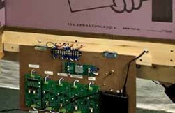
A little time out was taken to install the power management, and auto reverser circuits for the trackwork. These were installed in the center of the track donut, so they could be hidden but accessible. Then back to the pink foam and Shaper Sheet mountain construction. In working with the scenery materials, sometimes a surprise presented itself. What was envisioned as a tunnel became a peek-a-boo canyon. This construction was coincident with the COVID shutdown and materials shortages. The materials were sourced from suppliers from all over. This was the next phase of the project, and it needed to be done. The system allowed for modular construction around the track with assembled sections of Shaper Sheet mountains to be installed above the track. With additional pieces, the mountain assemblies could be blended together into a seamless range. The adhesive used for this construction was DAP 230 caulk. A rotary cutter was the best tool for trimming the Shaper Sheet material. This is a fabric cutter with very sharp replaceable blades. The covering for the sheet materials was Shaper Sheet Plaster. This has a short working time, so best done in small batches.

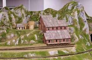
The mine module, showcased last year, has come along way. The area is now sceniced with ground cover. A tip on angled applicator bottles helped in dealing with the steep slopes which makes the scenery want to run away. The earth materials are location specific, as the dirt and rocks were obtained during a photo trip in the area. The presentation continued with a number of scenes from the railroad with comparisons to the progress over a year.

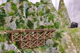
One track planning difficulty was operating the turnouts on the railroad. The physical separation was too great and tortoise switch machines were added. They were located off the track with remote activator rods as the area below the turnouts at this point were mostly filled. In another lesson learned, Scott discovered weathered Micro-Engineering track was too difficult to work with, and he converted to Peco track. He needed to weather the track and tried Micro-Engineering rail weathering solution to no avail. He ended up hand painting the entire track prior to ballasting.
As the track plan evolved, the staging yards were dead ends, and the attempt at a turntable was not successful. The solution was to add upper and lower loops to the staging yards to turn trains and added storage as a bonus. As was noted by the audience, the railroad lacks water. The difficulty was the stacked track plan would have needed three bridges lined up to accommodate the water. This was not desireable. So the water was omitted. The railroad will get some water in the future, but likely just a low water feature crossed by a trestle.
March Clinic – March 20, 2023
Tips and Techniques for Building Dual Gauge Turnouts Using Fast Tracks Assembly Jigs
Not many options exist these days to purchase ready to run dual gauge turnouts in any scale. For those wishing to design a layout around dual gauge operations, Fast Tracks assembly jigs offer a great way to build your own reliable and relatively economical turnouts at your bench and drop them into your layout. Special skills are not required to build your own turnouts, however, this presentation seeks to offer some tips and techniques I’ve found to be helpful in using the Fast Tracks assembly methods.
Tom George Biography

Tom George is a retired aerospace mechanical engineer of 34 years. He is married to his wonderful wife Cristy and enjoys both fresh and saltwater fly fishing, e-biking, hiking, and spending time in their condo on the beautiful Florida gulf coast. He currently has a business restoring and building brass model trains specializing in Santa Fe, Colorado and Southern, and D&RGW prototypes. He is also a long standing member of the Lockheed Martin model railroad club, better known as the Scenic Line Modelers.
Tom George was kind enough to present a clinic on hand laying turnouts and most importantly constructing dual gauge turnouts. Mr. George is an active member of the Lockheed Martin model train club, and a couple of years ago, they decided turnouts in the yard needed to be replaced. There were some turnouts that were not operating reliably, and there was a mixture of third rail to the right or left turnouts. The clinic focused on tips and techniques to speed the construction of the turnouts using Fast Tracks turnout fixtures, point building tools, and ties for turnout construction. The clinic focused on dual gauge turnouts, but the tips can be used for all turnout construction.
Railroads in Colorado had a number of terminals with dual gauge track. The dual gauge yards were used for freight transfer and lead to engine servicing areas. These could be found at:
- Denver
- Salida
- Alamosa
- Montrose
- Mack
A question comes up on why model dual gauge operations? The visual difference between standard and narrow gauge is striking with emphasis on the diminutive size of the narrow gauge equipment. The mixed operations offers a unique perspective on Colorado railroading. A couple of definition clarifications need to be made. A switch in prototype railroading is the movable portion of the turnout and the throw mechanism. A turnout in prototype railroading is the entire assembly of the operating turnout. This includes the switch, the frog, points, all fixed rails, guard rails, and any operating machine. Model railroaders use the terms interchangeably, but using turnout saves the term switch for any electro-mechanical mechanisms that work with the turnout.

For a true prototypical modeler, templates used by the railroads for construction of turnouts can be obtained through archives, historical books, and operating railroads. These show a plan view of the turnout with dimensions, and a material cut list for the components of the turnout. These give a real sense of the complexity of railroading, and the organization necessary for consistent operations. Fast Tracks has scale templates available on their website, https://www.handlaidtrack.com/. These templates may be printed to use in planning and bravely used to physically construct a scale turnout.
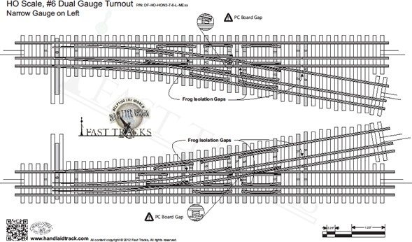
The template is quite complete showing the PC board tie locations, and the board gaps that need be cut in the copper cladding of the tie. This template shows the narrow gauge to the left. For the layout, it was determined the yard should be laid out with the narrow gauge to the left. This eliminates the need for cross overs to move the narrow gauge from the left to the right. As can be imagined, these turnouts and any crossovers need to be transited at low speeds.
Prior to Fast Tracks, model railroaders needed to hand lay turnouts, and usually, this was completed in place on the layout. A positive aspect to this method is the turnout could be made to fit any track geometry. The frog was made to whatever matched the track alignment. It could be a number 5 frog or a number 6½. This method required a great deal of skill to construct a reliable turnout. Shinohara made commercial dual gauge turnouts in HO.
Unfortunately, the business wound down operations in 2018 with the retirement of the owners. Some components are still available in the secondary or used markets at greatly inflated prices. Some cottage industries emerged that would custom make turnouts at increased cost and with long wait times.
In comes Fast Tracks with their assembly fixtures. These fixtures are precision machined in aluminum blocks to accurately hold and space the PC ties, the rails, and the frog. This lends a good deal of consistency to the turnouts and can be tuned for reliable operation. The turnouts can be built at the workbench, and when the tooling is amortized, the cost is dramatically reduced. The fixtures can be had in a variety of rail sizes and a wide variety of unique configurations for the special situations or alignment needs.
A list of tools and supplies needed for the construction of the turnouts include: From www.handlaidtrack.com;
- Assembly fixtures – one for each type of turnout needed.
- Stock rail and point/frog/toad filing tools – useful even if not using the assembly fixture.
- Quicksticks laser cut switch ties.
- Machined PC ties.
- Fast Tracks Points Shaping File.
Available from a number of vendors;
- Solder wick.
- Stay Clean soldering flux.
- Weller 35 watt soldering iron (a light blue professional grade).
- Xuron or similar quality Rail Nippers – pliers that shear instead of “smash” the rail, will need to be replaced when the action is no longer crisp with a clean cut.
- Sharp files, 10″ mill bastard.
- Jewelers saw.
- Pliobond adhesive – a contact cement for rail and tie bond.
A couple of optional tools;
- Bench top belt sander.
- Dremel Tool with various attachments.
Specialty item;
- P-B-L “Trick 10k” solder, available at https://www.p-b-l.com/ – a high shear strength solder suitable for repetitive motion applications.
Mr. George walked us through the list, indicating the use of each item and the reasons for the need for quality turnouts. The assembly fixture jigs were noted before and give wonderful consistency to the rail and PC tie placement in the turnout. The filing tools hold the rail in alignment as you hand file the rail for fit up. Again, these tools help with a consistent end product for the railroad. The machined PC ties are precision cut for the jigs, and have the same thickness as the laser cut switch ties. These items used together provide for a smooth turnout surface. The laser cut switch ties are thin plywood laser cut to tie shapes. The tie assembly is one piece, so the modeler does not need to handle individual ties to space them correctly. Rail nippers are important for trimming the rails to make up the turnout. The files noted are important to not only clean the cuts, but also for shaping the individual parts making up the assembly. The fast tracks point shaping file, or feather edge file, is unique in the edges of the file are taper cut to a triangular cross section. This helps to shape not only the points, but also final dress the PC ties copper cladding gaps. The choice of the solder and flux is important for capability. The solder joints are subject to stress from the rail, and the action of the turnout, so the high strength materials are appropriate in this construction.
More construction tips were added to the presentation. A tiny sharp metal chisel point tool is used to hold the rail in contact with the PC tie while soldering. Dremel tools should be used for other grinding chores. Hand files are best for rail shaping. Sharp hand files can do the work quickly, but remember files work only on the forward stoke, so file and lift. Use a card file often to remove filings from the file teeth. Brushes and even a sharp hobby knife blade can be used to clean up the file for maximum production. File a slight radius on the guard rails to prevent snags when cleaning the rails. Dress up the ends of the rails for a smooth transition and prevent flash from interfering with the construction.
In terms of soldering, use only enough heat to complete the joint. With the recommended solder, flux, and iron, it should only take a few seconds to complete the joint. Apply a bead of solder to the tip of the iron, and use to make the joint. Excessive heat can delaminate the copper foil and render the tie useless. Hold the rail on the tie until the solder hardens, so the rail does not move off alignment. Use 60/40 rosin core solder to tin and maintain the tinning of the soldering iron tip. Wipe the tip and re-tin often to preserve the tip effectiveness. Keep extra tips on hand to replace the tip as it becomes corroded. The use of the P-B-L “Trick 10k” is recommended for the turnout construction. This is a high strength solder to resist the stresses induced on the joint by rail movements, and residual stress built into the rail by the shaping process. Use a small brush to add just a little flux to the joint area, and use control to keep a small amount of flux right at the joint, so the flux does not spread over the tie and the rail. In applying the solder to the joint, a small amount of solder is all that is necessary. Nick the solder with the tip to get a small bead for use at the joint. While soldering, it is prudent to use a fan or other air movement device to pull the fumes away.
To construct the turnout, lay in the stock rails first, and continue on with the frogs and closure rails. Fit in the points, add the remaining rails, and add in the guard rails. The final step is to solder the points to the throw bar. As you proceed with construction, it is important to use the NMRA track gauge to check the alignment and clearances of the flange ways, points, and track gauge. Rolling a wheel set or truck through the turnout is a good check of the smooth and consistent alignment. As you install the turnout in the trackwork, the force to throw the bending rail points is greater than hinged points on commercial turnouts. The switch machine will need to accommodate the force with at least stiffer wire or possibly a more robust switch machine or mechanism.
Pre-bending the rails to fit into the jig is recommended. As the jig shows how and where the points are to fit to the stock rails, if you mark the length of the interference with a Sharpie fine point marker, the filing task is much easier. Remember in all of this to fit and test fit often. The frog should be constructed prior to adding the PC ties into the jig. This gives the modeler the best visibility of the frog joints. Using the filing jig as a weight aids in holding the frog components in position on the jig. Another critical area in the turnout for dual gauge operation is the “toad”. This is the area of the turnout where the wheel sets must cross over the diverging route so the through route maintains its course. Basically a combination of guard rails and rail gaps allow the wheels to continue on the desired routing. Spacing is critical as if any gap is too large or too small the turnout will become a derailment location. This is where the jig is of tremendous assistance.
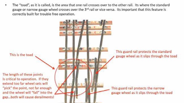
One of the final steps is to be certain the copper cladding is gapped at each location where a short may occur. The printable turnout templates on the web site illustrate the gaps in both the rails, and the copper gaps for each type of turnout. Here again, the gaps need to checked to avoid any voltage leakage.
For the really adventuress modeler, the turnout templates can be printed out to scale. Trim the template to fit, in this case on a coated MDF trim scrap, and use as the base for your turnout effort. It is useful to use the PC ties to build out the turnout. Cut and fit the rail, frog, and points carefully matching the template. This method accommodates the single use turnout on the layout, avoiding the cost of the alignment jig. After the turnout is constructed on the board, it is stripped off, and the residual paper template material may be cleaned to ready the turnout for installation. The example turnout is a three way narrow gauge turnout. The turnout is rather elegant.

Another example of hand laid turnouts is a curved #6 dual gauge turnout leading into the yard. This replaced a troublesome turnout. Since the surrounding geometry and roadbed was established the turnout was built off the layout with a tracing rubbing made of the roadbed and track. It was possible to construct a paper template on the board, and construct on the bench and fitted later into the layout.
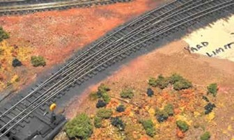
A #10 curved dual gauge turnout was constructed using similar techniques. With this size turnout, it is necessary to pre-bend the rail, particularly the frog rails to maintain the geometry as it is constructed.
Using the tools and jigs, a completed turnout can be completed in an hour and a half after practice. It is important to use the paper templates in conjunction with the jig to match up the locations of the rail gaps and the PC tie cladding cuts to electrically isolate the rails. In order to solder the throw bar into the turnout, one needs to keep solder off the mating surface of the points and stock rail. Using construction paper on the protected side to keep flux and solder from the area is a necessary step.
The FRD thanks Tom George for this enlighten clinic on turnout construction.
February Clinic – February 20, 2023
Non-Flicker Lighting and Weathering Locomotives
Bill Botkin will present two topics for our February Meeting. The first is Non-Flicker Passenger Car Lighting Circuits. Where he will describe how to build and install a non-flicker lighting circuit for passenger cars that is powered by DCC track power. He will also describe simpler circuits in an application for caboose markers.
Bill will continue with a presentation on weathering locomotives. During this segment he will describe techniques for weathering diesel and steam locomotives using washes, airbrushing, and dry-brush methods.
William E. Botkin Biography
Now retired as Vice President of AT&T Broadband’s Telephony Product Management group, Bill Botkin had national responsibility for developing telephony business requirements, introducing new products and services, offer design and pricing for local and long distance services. Bill was involved in the AT&T local telephony project since its inception in July 1998 in various capacities including marketing communications, sales and research. With over 25 years of marketing experience, Bill has worked in various industries including consumer photographic products, credit cards, mass transit, privatization of juvenile corrections and cable television.
The February edition of the clinic was a two part presentation. Bill Botkin started the clinic by reviewing his love of trains and his photographic adventures throughout the U.S. and further in foreign travel primarily to capture steam locomotives. He was again enthused about model trains while waiting for a train in Arizona. He picked the Erie Lackawanna railroad to model specifically during 1952-1953 near Port Morris, New Jersey. He was able to show several scenes from his railroad and related during his college years worked during a summer for the Lackawanna at Port Morris.
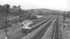
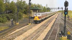
He and his wife volunteered at the Colorado Model Railroad Museum in Greeley. As a result of the friendships developed there, they became interested in operations. They now operate nearly every Saturday somewhere along the front range. The opening presentation was on LED Non-flicker lighting circuits. The information was presented by Bill on a circuit design by Victor Hand. The circuit is adaptable to passenger cars as well as caboose lighting efforts. The flexibility to locate the LEDs within the cars to light portions of the cars yields remarkable results.
Modeling early 50’s means your railroad will have a sizeable fleet of passenger equipment. These cars will need to be equipped with several elements to add realism to the operation. One will need interior details in plausible colors, passengers to add a believable reason for the passenger train to operate, window shades at varying heights, and car lighting to show off the interior of the cars.
Click “here” to download “Non-flicker Lighting Circuit Handout.
Bill compiled a list of lighting requirements for passenger cars:
- Utilize track power.
- Non-flickering circuits for constant operation.
- Ability to place lights in locations appropriate for the individual car.
- Simulate incandescent and fluorescent lighting tones for the car type.
- Adjust the LED intensity for layout lighting.
- Operate the lights without a mechanical switch or decoder.
- Economical to build.
We were taken through an explanation of the circuit or “how it works”. Walking along the circuit, the first element is a bridge rectifier which converts the DCC track power at 14.25 Volts AC to 14.25 Volts DC. Following the rectifier are two magnetic reed switches to activate the relay to turn circuit power on-off. As is illustrated, these are optional elements that can be omitted to allow an always on circuit. Next element is a DPDT relay to control the capacitors and the LED circuits. The following elements are the super 5.5 volt capacitors which are wired in series to handle up to 16.5 volts. These are the parts of the circuit which allow the non-flicker operation and extend the length of the power off lighting. The circuit continues through a voltage regulator to trim the capacitor voltage to 3.3 volts for the LED operation. The voltage is further controlled by a trim potentiometer to adjust the brightness of the LEDs. Each LED can be further adjusted by adding in a resistor in series with the LED to achieve individual brightness in certain locations within the car.
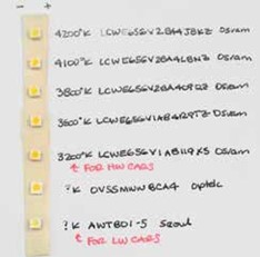
The circuit components are shown on the hand-out for the clinic which gives the supplies needed and circuit diagrams for three circuit types. (Handout is included in the Telegrapher transmittal email.) The largest variable in the circuit is the LED “color temperature” which determines whether your view of the lighted car is flourescent or incandescent. The recommendation is to order a small quantity of a variety of LEDs in varying color temperatures and compare your view of the performance. In that fashion, you can determine the ones you need. Be advised the part numbers and LEDs change often, so the part number you determine at one time may not be replicated in future. You will need to download from your LED supplier the specification sheet for your LED to determine the cathode and the anode location on the LED cube.
The components and a completed board can be seen below.

The perforated board is cut to 5/8” wide by the length of the car for HO installation. Note the size and thickness of the capacitors shown. It was noted that some trimming of the partitions within the car may be necessary to fit the board over the interior and below the car roof.
Within the handout material is a listing of useful items to assemble the boards. Two of the items are a 12 watt soldering iron and low temperature solder. These are very helpful in soldering the LEDs into the circuit as the higher temperatures tend to damage the LEDs. The flexibility of LED placement on the board allows adjustment to light only the areas you determine. You can light individual compartments in sleeper cars leaving others dark. Corridor areas, food preparation areas, and restrooms may all be separately lit with a user determined intensity. For ease of maintenance, Bill wires the board through disconnects to the trucks. This allows removal of the board or repair of the trucks. The board sitting on a heavy weight car highlights the thickness of the components and how clearances can be attained. Also, the use of window shade material and passengers helps with the illusion of a revenue producing car.

Bill uses Walthers passenger car trucks for his cars to simplify the wiring to get track power to the board. He simply connects a flexible wire to each side of the truck, and runs the wire to the disconnect within the car. By using flexible wire and enough slack the car can run true through turnouts and around curves. With other trucks, Bill uses bronze wire as a sweep against the wheel or axle to pick up power, and attaches the sweep to a flexible feed wire into the car. He generally wires both trucks for power pickup to eliminate consistency issues. Extending the feed wires up from the trucks into car requires the wires be routed to disguise the locations in the car, so one must find hidden corners to route the wires.
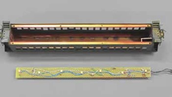
Brass passenger cars have some difficulties in installing a board as the roofs are not removable, and so the work needs to be done from the floor area. This may necessitate removing bracing within the car to position the board and install an interior. The trucks on the brass cars were replaced with Walthers trucks as the original trucks were found to be unreliable. The board was fastened to the roof of the car with double sided foam tape which not only anchors the board, but insulates the circuit from the brass roof.
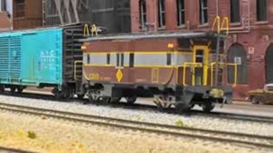
The simplified circuit without the switches and potentiometer was shown and is included in the handout. (Handout is included in the Telegrapher transmittal email.) This style of circuit is intended for caboose marker lights or other instances where the flexibility of the switched circuit is not required. The example shown is a Erie Lackawanna caboose with marker lights at each corner. The lights are a lunch box shaped housing with red marker lights. These light assemblies were fabricated with a square styrene shape cut to length and drilled for the light exit. A light pipe was attached to a red LED and anchored with shrink wrap tubing. This resulted in a marker light at each corner of the caboose.
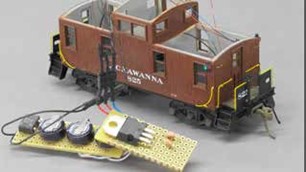
The next installation was in a standard caboose utilizing Tomar marker lights. Since this is a shorter car, the board needed to be cut in half to fit the caboose interior. This is a hybrid circuit with the switches and latching relay to allow control of the marker lights for the car. This circuit is shown in the handout. (Handout is included in the Telegrapher transmittal email.) Note: Tomar lights are still available through Walthers. The resistors which suited Bill were 2.4K Ohm, which gave the intensity desired. There was a question on how the boards were secured in the passenger cars, and Bill uses Kapton tape over each end of the board.
Click “here” to download the Model Railroad Craftsman article by Bill Botkin.

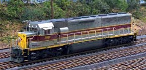
The next topic of the clinic was weathering locomotives. Bill volunteered at the Colorado Model Railroad Museum in Greeley, actually before it opened. He noted the locomotive fleet was not weathered and was toy like, so he went to work to weather the fleet. It was at this time over 150 locomotives. He was able to show at the clinic several of the locomotives he worked on during the weathering period which was about two years. The techniques were developed over the course of the weathering to enhance the details of the model, and provide a real world look to the railroad. The first item on weathering is determining the extent of the weathered appearance. Do you want a light weathering or a more aggressive weathered look. The best element to weathering is practice, practice, and more practice. Get a less valued piece, and practice the weathering techniques on that model. It is important to note the techniques described were used on HO scale equipment. Billl uses an airbrush for his weathering and interestingly he uses Floquil paint, discontinued by the manufacturer. He described his setup and safety equipment. This includes a paint booth with an outside exhaust, a partial face respirator, nitrile gloves, and safety glasses. His paint booth was constructed based on plans in Model Railroader magazine. Importantly, the blower was the industrial model specified in the article and sourced through Grainger. His weathering is based on prototype photos with the best being a photo of the exact locomotive you are weathering, or as an alternate one of the same series of locomotive purchased by the railroad near the same time. The internet is a valuable source for the prototype photographs. Some include: https://www.american-rails.com/fallen-flags.html, https://www.railpictures.net/us/, and https://morningsunbooks.com/. The Morning Sun Books are pictural books of specific railroads, categories of locomotives, and railroad equipment. By studying the photos, one can get a sense of where on the rolling stock you will find the mud, dirt, truck coloration, and fuel tank markings. The first step in weathering is a wash. The preferred paint is solvent based material, but artist oil paints can be used to good effect. As mentioned, the airbrush is used with very thin paint. A dry brush technique is used for accent areas and markings. In building up the weathering, weathering powders and pastels are used to replicate the drainage patterns off the equipment. The final step is to seal the weathering with a Dull Cote or similar dull finish sealant. For specific items to be weathered, it will need to be disassembled. At the least, the shell needs to be removed. That frees up the trucks, fuel tank, and other running gear to be processed with the weathering materials. The trucks are disassembled to allow the side frames and the wheels to be separately detailed. The wheel faces, fuel tanks, and truck side frames are painted with a combination of grimy black and roof brown. Washes are used over the vertical surfaces to simulate the rain/water effects on the equipment. These washes are made with engine black and thinner in a 50/50 ratio using a wide flat brush brushing vertically on the surface with a dry brush technique. Work in light passes letting the work dry before continuing. You want to build in fine layers as you may continue to add, but it is difficult to backtrack the effect.
Moving into steam locomotive weathering, the weathering mix tends to be reefer grey and thinner as the engine black weathers to a grey. Basically the weathering runs down the sides of the locomotive from the top. The areas around the sand domes and hatches where the material can leak or spill are better treated with a tan wash. The areas of the locomotive and tender where the scaly water leaks or runs are better treated with a white/grey mix weathering to match the prototype. Here again, it is important to study prototype photographs to replicate the effects.
Working on the shell with an airbrush means that you need to mask certain areas of the details. The windows and headlights/rear lights need to be masked off as these are regularly cleaned.
The masking does not need to be too precise as long as the clear areas are covered. The overlap of the masking provides a little more effect to the weathering coat. The roofs of the diesels begin their life as a primarily black surface but quickly weather to lighter colors and a mottled appearance. Here the weathering coat can be the grey tones, but not a uniform coat. The engine exhaust area will be black from diesel soot, trailing away from the area in the primary direction(s) of travel. To continue the weathering, use a variety of colors in the 50/50 mixture, like dust, earth, rail brown, and grime. These are added randomly on the shell to give variations to the color scheme and replicate the areas where grime is deposited on the working locomotive. These effects are added from the bottom of the locomotive extending upward.
The pilot has streaks of road grime at the wheel locations and overall grimy appearance as this is the leading edge of the locomotive. There is always a question on whether to paint the couplers or not. Bill paints the couplers with a dilute weathering mixture of rail brown and rust. He then focused on the bow wave. The weathering on the sides of the locomotive tends to take on the shape of a bow wave from a boat. It starts at the front of the engine and arcs up the sides and tapers off toward the rear of the locomotive. You will find this on virtually all locomotives, and it shows up well on the Amtrak locomotives with the slab sides. The exposed walkways on the locomotives tends to be very light colored not withstanding the base color of the walk. By experience, the Bragdon weathering powders work the best to attain the light coloration with control of the location. Again, this application should vary as the real world shows a lot of variance. In the area of the fuel filler, a dark shiny black stain is usually found. This is actually a mixture of dirt with the spilled diesel. This is another rather indistinct area on the fuel tank created by using a thick brush with engine black dry brushed at the location of the filler. This discoloration can be found on other areas of the fuel tank depending on the prototype. This is another instance of checking the prototype photos for the fuel tank or other discolored areas on the locomotive. Other areas can be enhanced by dry brushing is the addition of rust to the brake shoe area, and black/grey colors added to the handrails, particularly on the vertical runs where hands would grab the rail.
In making up a lash up of locomotive units, it is a good idea to review the units for variation. One does not generally see a uniform appearance to multiple units. The final coat to all this work is to seal the area with a dull finish such as Testors Dullcote. One can use other matte finish paints, but it needs to be plastic compatible, and be certain it is a matte finish, not a semi-gloss or gloss.
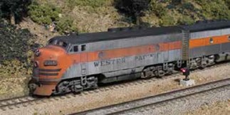
The last example of diesel weathering was severe weathering on a Western Pacific diesel where the initial wash coats dissolved the lettering on the unit. Bill stopped the washes, and asked about replacing the unit or something else. He was told this was fine and should continue on. So, he did, and it resulted in a unit that unfortunately closely resembles a Western Pacific locomotive. The “Old Wobby” was always in financial difficulties, so the rolling stock only looked good once during its career with the railroad, on the day of delivery.
Bill walked us through some more examples of steam locomotives. The overall appearance of a steam locomotive is a lightly streaked grey/black with instances of dirt and water scale coming down the sides. The running gear is dark grey with black at the lubrication points. The weathering of the running gear is best done while the loco is running at a slow speed. The study of prototype photos particularly of the engine type is necessary to get the weathering to resemble the prototype.
He uses a Badger dual action airbrush for his weathering work. It is important to work slowly in thin layers. Too much, too fast yields unsatisfactory results. The discussion covered a number of other topics but of interest is the reference to: http://modelmemories.com/, to find speed signs for the Erie Lackawanna railroad. They supply a number of detail parts as well as these signs, so check them out for your HO and O scale needs.
January 2023
How to Become a Published Author
Jim Chiddix’s interest in building a model of the Oahu Railway (1889-1947) led to a mountain of material; ranging from photos from many collections, newspaper articles from the day, and data and blueprints from the corporate records of the railroad and suppliers of its locomotives. This was augmented by interviews with people who had
ridden the railroad, or had relatives who had worked there. Organizing that information into a coherent illustrated history of the railroad was a rewarding adventure for his coauthor, an old friend from Hawaii days, and himself. The mechanics of getting all of that into a form ready for the printer were an education, and the result has turned out to appeal to those with an interest in Hawaiian history as well as train buffs, especially those focused on narrow-gauge railroads. Jim will describe the steps leading to publication in some detail, and will distribute copies of the final product to any attendee who’d like one.
Jim Chiddix Biography
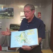
Jim Chiddix followed a career beginning with an interest in model trains and amateur radio; led to engineering school and technical work in the Army. He ended up in the nascent cable television business in Hawaii fifty years ago. A job at a small cable operation in rural Oahu gradually evolved into a post as chief engineer at Time Warner Cable, where he was deeply involved with the adoption of new technologies, including fiber optics, digital video, high-speed broadband, and streaming television services. Following the unhappy combination of Time Warner and AOL, he went on to lead a San Francisco-based company, OpenTV, that provided set-top box software to cable and satellite television operators around the world. After the sale of OpenTV, Jim retired, but joined a series of technology company boards. He and his artist wife, Trudy, split their time between Evergreen, Colorado, and San Francisco. His On3 model of the Oahu Railway & Land Company is gradually taking shape in their basement.
Jim Chiddix’s wanderings took him to Hawaii in 1971 with a venture in a charter trimaran, the Seraphim. When that didn’t work out, he got involved in Cablevision in rural Oahu. That was the way he was able to live on the island of Oahu, but his wanderings about the island lead him to evidence of an abandoned rail system. The railroad was the Oahu Railway & Land Company. The quest for mainland TV found him involved in a satellite earth station and a larger cable company in Honolulu. He was always interested in model railroading, and this narrow gauge railroad on the island kept his interest leading to a model railroad in Evergreen, Colorado. The backbone of the prototype railroad were the agricultural products grown on the island. Pineapple and sugar cane were grown on sections of the island where the soils, and microclimate were suited for these products. The farms had an internal rail service that collected cane and pineapples from the fields, but the connection to Honolulu Harbor was via the Oahu Railway. The Oahu rails stretched from the Honolulu harbor around the island to the west and to the north coast at Kahuku. A spur line ran north from the west edge of Pearl Harbor to the vicinity of Wahiawa. The Honolulu Harbor area was home to the railway’s headquarters, roundhouse, engine servicing facilities, coach house, and Honolulu Station.
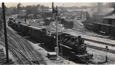
The area also hosted industries including Libby, Dole, and Del Monte canneries. Unfinished sugar was gathered on the Oahu Railway in box cars making its way to the Harbor and into California for final processing, distribution, and sale. All should remember C(California) and H(Hawaii) Sugar. Jim’s research led him to the Hawaii State Archives. There was a large collection of maps, photographs, history books, and pamphlets. Nearby the Archives is the Hawaii State Library which contains a collection of all the newspapers from Hawaii on microfilm. Jim and his friend, MacKinnon Simpson, who had just published a book on streetcars, skimmed all the newspapers from 1889 to 1947. The purpose was to find articles, advertisements, and other railway information to include in their book, “Next Stop Honolulu! The Story of the Oahu Railway & Land Company”.

The next research stop was the Bernice Pauahi Bishop Museum, the designated Hawaii State Museum of Natural and Cultural History. The Railway on its abandonment donated all the records of the railroad to the museum for preservation. This was a large collection of boxes and boxes of records including the chief engineers’ records of surveys, construction notes, and operating information. The corporations’ annual reports were included in the documents which gave information on the corporate activities for each year.

Jim collected a number of photographs on the Oahu Railway and plantation railroads. The collection has over 2000 photographs. These images were generously donated as Jim scanned the photos and returned them to their owners. He has a website, www.oahurailway.com, with many more photos than are reproduced in the book. The trove of research included builder photographs of the locomotives. The earlier versions were Baldwin locos, but the later locomotives were ALCO locos, very similar to D&RGW K-28’s. The locomotive power also included two Shay locos for use on the rails in the middle of the island. The newspaper articles they copied from the library microfilm were scanned, and the white on black reversed to black on white. Utilizing Photoshop, the results could be cleaned up, and the article yellowed to resemble an old newsprint article. A number of these images were included in the book to give readers a sense of the railway, timetables, special excursions, construction articles, and historical pieces. This is an interesting look at not only the history of the railway, but of island life during the operation of the railroad.
Large format panoramic photographs were located in the state archives showing the Honolulu area in the 1920’s. By stitching these together and colorizing the print, a backdrop for the model railroad was developed. The final print was 3 feet high and 180 feet long and was able to be wrapped around the model railroad room and brings a real sense of the island in 1920s in the space.
As can be imagined, it took several years to research and gather the material. Further, it took several years to write the text and assemble the material into the book format. John Coker painted an original art piece showing a passenger train leaving the Honolulu depot for the dust jacket. The book was laid out using PageMaker software, placing the text and photographs into the correct places and with the correct font. The book needs to be made ready for printing where the photographs are rendered into a series of small different color dots. This allows the book to be printed without smearing the images as the paper flows through the press. A printer in Hong Kong took all the materials which had been copied onto CD’s and processed all the photographs. Ultimately, the printed books, “Next Stop Honolulu! The Story of the Oahu Railway & Land Company”, were completed and shipped to two locations for storage and distribution. Some went to Hawaii and others to a warehouse in California. The books arrived 320 books to a pallet for a total press run of 5000 books.
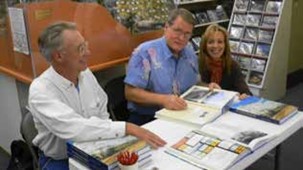
The book was launched at the 2004 Narrow Gauge Show in Santa Clara, California. The narrow gaugers were intrigued by the narrow gauge on an island, and again one was not the Rio Grande. Later, they staged a book signing at Caboose Hobbies in Denver with John Coker in attendance. Jim worked with a number of book distributors, one in Hawaii and others on the mainland. As time went on, he even sells through Amazon. He is actively displaying at train shows, like a garden railroad show or especially narrow gauge conventions and shows.
Jim brought several copies of the book which he had tabbed to go along with his presentation. These tabs marked pages of interest in the clinic. The front piece of the book has a color illustration of the Island of Oahu showing the extent of the railway and the interconnecting plantation lines. The coverage of the island is concentrated in the agricultural areas. The next tab was the colorized piece derived from a black and white archival drawing. It shows a train pushing its way inland. A black and white period photo of Benjamin Dillingham is included in the preface of the book. An interesting side note to this book and the focus on the Dillingham rail company is it led to Jim meeting with the grandchildren of Benjamin Dillingham. The railroad is woven throughout the history of Hawaii. When the railroad started, Hawaii was a sovereign kingdom. During the agricultural business growth on the island, the immigrant population over threw the Hawaiian Queen and lobbied the U.S. to accept it as a territory. The territory allowed for rapid business growth and profitability as this removed the high tariffs levied against imported goods. The other motivation for the U.S. was the acquisition and construction of Pearl Harbor. The former mud flat was transformed into a world-class harbor and naval base. The following tab is a transformed copy of a newspaper article covering one of the excursion trains which ran in an 1889 newspaper. The article came from a microfilm copy which was converted from white on black to a black on white article. It was scrubbed through Photoshop to clean up the text and colorized to give it the look of old newsprint. The edges of the article were torn to resemble a tear out from the news and further colorized to give it an aged appearance. The result is a striking resemblance to an old clipping saved by someone. This gives us an idea of the lengths Jim went to create a historic piece. The next item is an artist rendition of a black and white photograph transformed into a color painting of a passenger train reflected in a rice field. The book could not cover the railway without a photo of cars loaded with pineapple, and the stacks of pineapple crates awaiting movement into the cannery. In order to replicate this scene on the model railroad, Jim has friends making 3D pineapples and laser cut car sides to build 50 pineapple cars. Since they need to grow on something, Jim has planted 2000 pineapple plant replicas with a pineapple atop each plant. A railroad couldn’t operate without a timetable, so within the book is a summary of timetables which gives a glimpse at the activity on the rails along with fares and some speed limit information. Of interest are notes which indicate the number of flag stops as well as regularly scheduled stops. A replica of a standard timetable is included showing the complex movements on the line.
During the pineapple season for example, they would run 70 trains a day into the fields and return. To accomplish this, the railroad installed block signals to allow the operation with 5 minute headways. Another black and white photograph was colorized and included in the book showing the drama of black smoke being issued from the locomotive as it makes its way down the tracks. The book includes a section on the locomotives found on the railroad, which was about 30 locos. Each photo is accompanied by information on the builder and where on the railroad it was used. The information can be used to kit-bash commercially available model locomotives into power on the model layout. Included within the pages is locomotive number 90 which is a K-28 look alike with the air pump on the side and an oil tender to fit the fuel available. In the background of the photo, one can notice a fuel/water rack with a moveable sand cart. Also, it should be noted the locomotive is equipped with two sand domes. This is to allow for the use of sand over the pineapple juiced tracks. In the late 1920’s, the railroad was worried about the decline in passengers, so they added motor cars to the fleet. These were gasoline powered railcars with lower operating costs. An inclusion in the book is a section on rolling stock. The railroad rostered 1200 cars of various sizes. A summary of annual report “nuggets” is included to illustrate the growth of the railroad, and the challenges it faced in a difficult operating environment. The book concludes with acknowledgements, bibliography, and an index of individuals. An undertaking of this magnitude would not have been possible without the resources included in these pages.

Jim moved into scenes from the model railroad, where Don Meeker built a fabulous model of the Honolulu passenger station, including a system map and timetable found on the wall of the station in the open air waiting area. In that area of the railroad is a dock fabricated by Tom Gillian including code 70 rail spiked into place on the dock. The scene is extended into the water with a model of an oil barge and a steam ship. Continuing into the layout room there is an open air shed, again 3D printed truss work for the roof and aluminum corrugated sheet roofing material aged to resemble rusted steel. A roundhouse and turntable add to the scene. For the agricultural scenes, Jim followed his scenery methods. The sugar cane was artificial wheat grass glued into a field adjacent a photoshopped sugar mill. The pineapple fields and loading area were created with artificial plants topped with the 3D printed pineapple. Palm trees were fabricated from cake decorating fronds added to tape wrapped wire and decorated with green peppercorns.